Control panel SP231
Configuration of control panel operation
©1997-2015 Trikdis
38
www.trikdis.com
6.13
PGM output configuration
The board contains five (PGM1
–
PGM3, BELL-, LED) programmable output terminals for connection of devices
controlled by the control panel.
Terminals PGM1
–
PGM3 are designed for connection of user selected modes, circuits.
Terminals BELL+ and BELL- (PGM4) are designed for siren connection. The control panel provides control
and signalling if external circuit of this output is interrupted, short-circuit.
Terminal LED (PGM5) which is connected to positive terminal of mains supply output via 5K1 resistor. It
is designed for LED indicator connection.
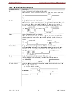
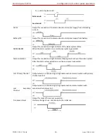
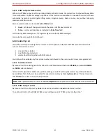
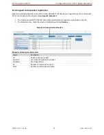
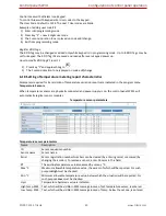
PGM outputs are set in program menu PGM. Any output can be set operating in one of numerous operation
modes (see 6.13.1 “PGM output operation descriptions”).
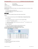
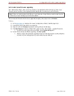
PGM output parameters
Name
Description
ID
Output sequence number.
PGM
Output name.
Output definition Selection of output operation mode.
Control Mode
Type of remote control mode, pulse or level.
Pulse Time
Pulse duration is indicated. Duration can be from 0 to 9999 sec.
Dial
Remote control by call of output set in Remote control mode is enabled.
PGM output parameters

