User Guide
TransCore Proprietary
4-2
General
Equipment should be installed/serviced by skilled, qualified personnel only. Equipment
should be installed in RESTRICTED ACCESS LOCATIONS only.
Mechanical
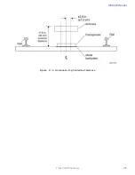
Dimensioned mounting hole drawing (metric & in)
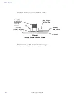
General info on screws, torque, etc.
Electrical
Power
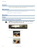
Assembling the Power Connector
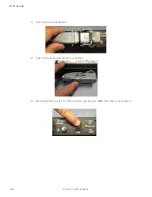
WARNING: Ensure ON/OFF switch is in “OFF” position and “PWR ON”
LED is not illuminated before servicing unit.
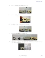
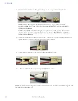
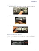
1. Unpack unit from shipping crate and locate the power connector on the front panel.
2. Unlatch plug from receptacle on unit and remove.
3. Locate set screw on the plug housing.
Summary of Contents for 1422E
Page 16: ...Before You Begin 1...
Page 20: ...AI1422E Reader TransCore Proprietary 1 5...
Page 21: ...2 System Overview...
Page 25: ...AI1422E Reader TransCore Proprietary 2 5 Figure 2 2 Antenna to Tag Centerline Tolerance...
Page 26: ......
Page 27: ...3 Interface Connections...
Page 32: ...User Guide TransCore Proprietary 3 6...
Page 33: ...4 Installation Instructions...
Page 41: ...AI1422E Reader TransCore Proprietary 4 9...
Page 42: ...5 System Test Procedures...
Page 45: ......
Page 46: ...6 Communications Protocols...
Page 49: ......
Page 50: ...7 Command Codes...
Page 87: ...User Guide TransCore Proprietary 7 38...
Page 88: ...8 Troubleshooting and Maintenance...
Page 93: ......
Page 94: ...Character Conversion A...
Page 96: ...B Technical Specifications...
Page 99: ......


