AI1422E Reader
TransCore Proprietary
3-5
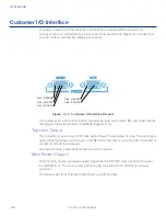
RF Power Output
The TTL RF power LED goes active high when the reader system is configured for the
RF power to be on and the ON/OFF switch is set to ON. The RF power signal may be
connected to an LED for monitoring purposes.
The main power relay is referenced to 5Viso and I/O Ground.
Trigger Signals
The trigger connection turns on the RF power when shorted to I/O ground and the AI1422E
Reader System has been programmed with the RF Follows Trigger command (!642).
Power Connection
The power connector on the front panel of the AI1422E Reader System is a panel mount,
right angle, EPIC ® HA-3 style 3pin plus ground rectangular connector.
Summary of Contents for 1422E
Page 16: ...Before You Begin 1...
Page 20: ...AI1422E Reader TransCore Proprietary 1 5...
Page 21: ...2 System Overview...
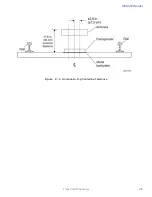
Page 25: ...AI1422E Reader TransCore Proprietary 2 5 Figure 2 2 Antenna to Tag Centerline Tolerance...
Page 26: ......
Page 27: ...3 Interface Connections...
Page 32: ...User Guide TransCore Proprietary 3 6...
Page 33: ...4 Installation Instructions...
Page 41: ...AI1422E Reader TransCore Proprietary 4 9...
Page 42: ...5 System Test Procedures...
Page 45: ......
Page 46: ...6 Communications Protocols...
Page 49: ......
Page 50: ...7 Command Codes...
Page 87: ...User Guide TransCore Proprietary 7 38...
Page 88: ...8 Troubleshooting and Maintenance...
Page 93: ......
Page 94: ...Character Conversion A...
Page 96: ...B Technical Specifications...
Page 99: ......

