User Guide
TransCore Proprietary
2-4
Transponders (Tags)
The AI1422E Reader System can use TransCore’s half-frame or full-frame read-only tags.
When selecting a tag for an application that requires the tag to be placed on the road bed,
several design elements need to be kept in mind. The beam powered tags will have a
shorter footprint than a battery or switch powered tag, and thus the maximum top speed
of the vehicle will be less, all other factors equal. However, although the battery tag has
an inherently longer footprint, the battery life limitation will require the operating company
to replace the tags every 8 to 10 years. Additionally, the presence of the battery and its
reactive mass reduces the reliability of the tag, particularly when the tag is placed near high
shock or vibration locations such as switches.
For practical purposes, the switch powered tags have RF characteristics similar to battery
tags, and the tags are powered by inductive power derived from railway switch power.
Tag Mounting
All of the tags used with the AI1422E must be mounted on a flat metal plate. The internal
antennas of these tags are tuned for the backplane of the tag to be in contact with a
flat metal surface. This metal surface does not need to be extended beyond the outer
dimensions of the tag, and having a larger metal surface will not affect the immediate
performance of the tag.
Metal located in the immediate vicinity of the tag, that is, to the sides of the tag or above
the tag. can affect the tag’s performance. Metal surfaces or objects should not be placed
closer than 1 inch (2.5 cm) to the side edges of the tag to ensure that the tag’s antenna
tuning remains within design criteria. Metal placed above the tag can cause shadowing of
the RF beam, both in the incident and return directions, and should be avoided. The only
exception to this rule would be metal placed for the purpose of effecting the read range
of the tag or footprint of the system, and the placement of such metal should be done with
careful planning and testing to ensure proper system performance. With battery powered
tags, the arrangement of intentional metallic obstructions may be the best way to limit the
broad footprint of these tags, as well as improve the repeatability of the TLS signal with
respect to its absolute position relative to the tag. These tag mounting details would need
to be made by the customer on the basis of each customer’s overall system design and
requirements. Keep in mind that metal placed too close in proximity to the tag will affect the
tag’s antenna tuning, and may unintentionally affect principal design parameters such as
VSWR or the impedance match of single paths internal to the tag, to name a few examples.
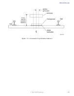
Antenna-to-Tag Centerline Alignment
For best performance mount tags so that the centerline of the tags and the centerline of
the reader antennas are within ±2.9 inches (±7.5 cm) of each other (
Figure 2 – 2
).
Antenna-to-tag Distance
Many installations have been installed with a nominal 11.8-inch (30-cm) distance from the
backplane of the reader antenna to the back edge of the tag (
Figure 2 – 2
).
Summary of Contents for 1422E
Page 16: ...Before You Begin 1...
Page 20: ...AI1422E Reader TransCore Proprietary 1 5...
Page 21: ...2 System Overview...
Page 25: ...AI1422E Reader TransCore Proprietary 2 5 Figure 2 2 Antenna to Tag Centerline Tolerance...
Page 26: ......
Page 27: ...3 Interface Connections...
Page 32: ...User Guide TransCore Proprietary 3 6...
Page 33: ...4 Installation Instructions...
Page 41: ...AI1422E Reader TransCore Proprietary 4 9...
Page 42: ...5 System Test Procedures...
Page 45: ......
Page 46: ...6 Communications Protocols...
Page 49: ......
Page 50: ...7 Command Codes...
Page 87: ...User Guide TransCore Proprietary 7 38...
Page 88: ...8 Troubleshooting and Maintenance...
Page 93: ......
Page 94: ...Character Conversion A...
Page 96: ...B Technical Specifications...
Page 99: ......


