User Guide
TransCore Proprietary
3-4
Customer I/O Interface
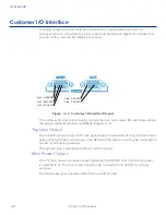
A mating connector for the customer I/O interface is supplied with each unit. This
connector allows a screw terminal, point-to-point wiring interface.
Figure 3 – 3
shows the
pin-outs on the customer I/O interface connector.
Figure 3 – 3 Customer I/O Interface Pin-outs
The customer I/O interface connector contains the lock, main power, RF solid state outputs,
the trigger signals (solid state), and RS422 (
Figure 3 – 3
).
Tag Lock Output
The transistor-transistor-logic (TTL) lock signal shows the presence of a tag. The lock signal
goes active high when a valid tag is in the RF field of the antenna and may be connected to
an LED for monitoring purposes.
The tag lock relay is referenced to 5Viso and I/O Ground.
Main Power Output
The TTL main power signal goes active high when the ON/OFF switch on the front panel
is switched to on. The main power signal may be connected to an LED for monitoring
purposes.
The main power relay is referenced to 5Viso and I/O Ground.
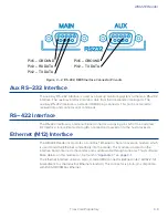
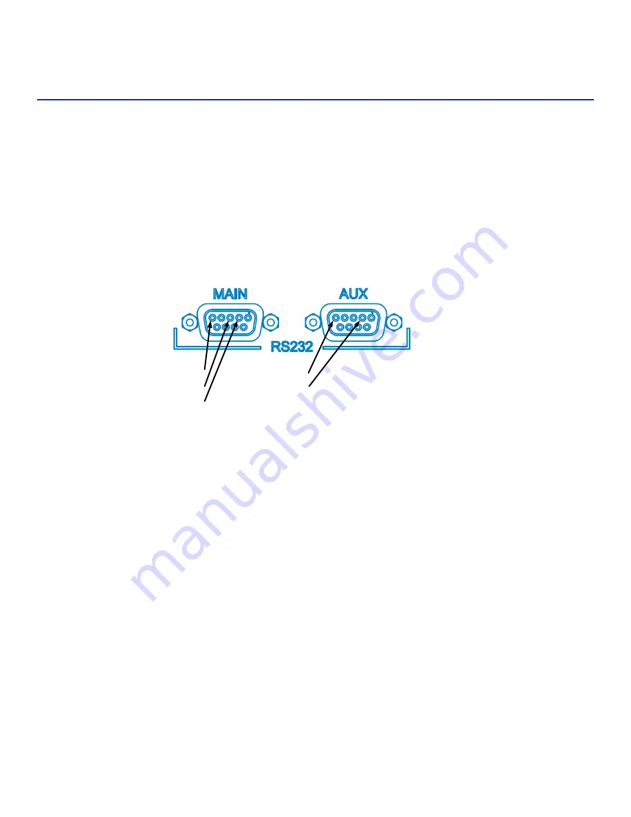
Pin5 – GROUND
Pin3 – RX DATA
Pin2 – TX DATA
Pin2 – TX DATA
Pin5 – GROUND
Summary of Contents for 1422E
Page 16: ...Before You Begin 1...
Page 20: ...AI1422E Reader TransCore Proprietary 1 5...
Page 21: ...2 System Overview...
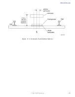
Page 25: ...AI1422E Reader TransCore Proprietary 2 5 Figure 2 2 Antenna to Tag Centerline Tolerance...
Page 26: ......
Page 27: ...3 Interface Connections...
Page 32: ...User Guide TransCore Proprietary 3 6...
Page 33: ...4 Installation Instructions...
Page 41: ...AI1422E Reader TransCore Proprietary 4 9...
Page 42: ...5 System Test Procedures...
Page 45: ......
Page 46: ...6 Communications Protocols...
Page 49: ......
Page 50: ...7 Command Codes...
Page 87: ...User Guide TransCore Proprietary 7 38...
Page 88: ...8 Troubleshooting and Maintenance...
Page 93: ......
Page 94: ...Character Conversion A...
Page 96: ...B Technical Specifications...
Page 99: ......


