19
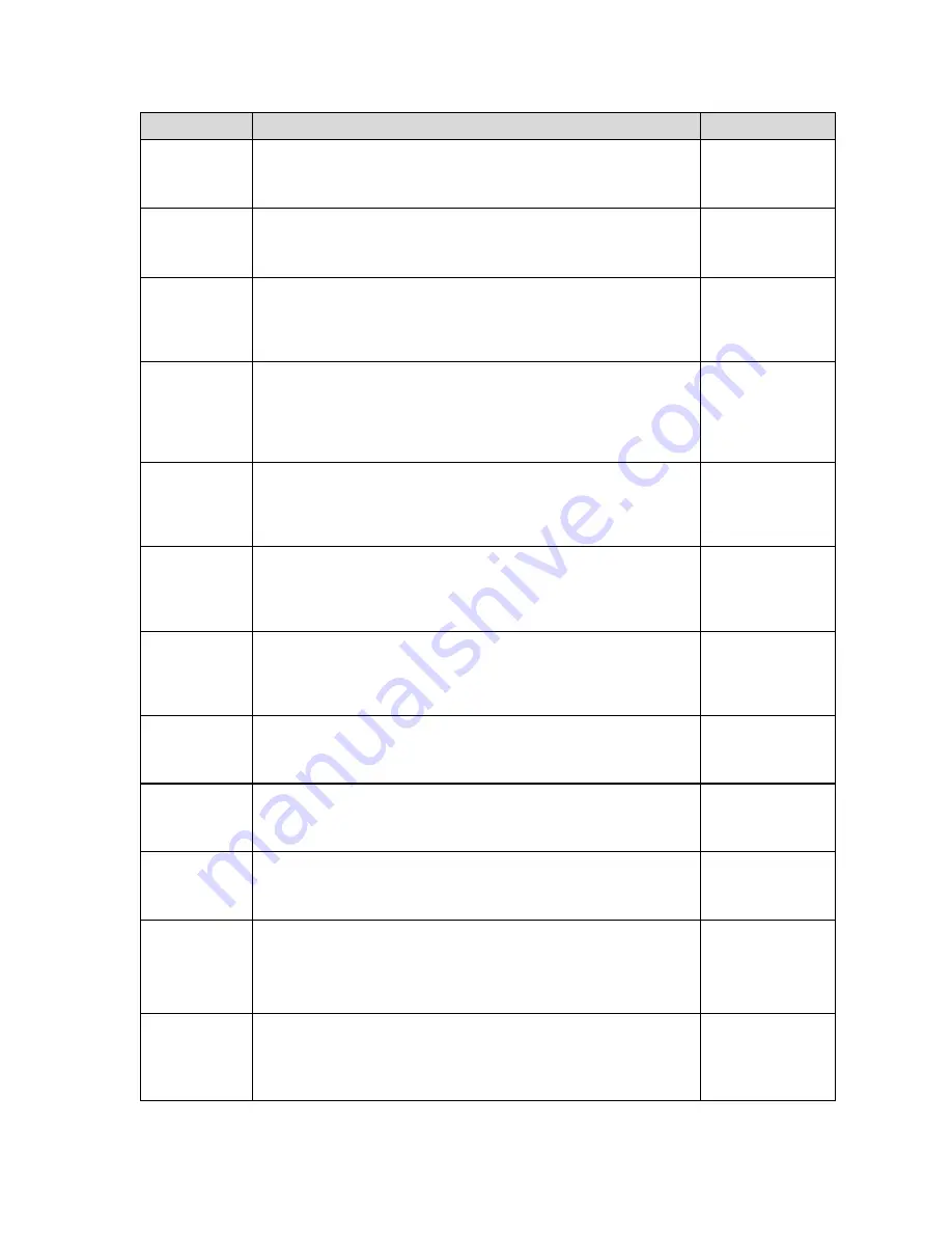
CODE/NAME
DESCRIPTION
SELECTION LIST
A1-8
Set ID Number
Allows you to key-in the ID number. Pressing the
ZERO
key to scroll
down one level begins the sequence.
Key-in
0 to 999999
123456
A1-9
Line Feeds
Allows you to key-in the number of line feeds. Pressing the
ZERO
key
to scroll down one level begins the sequence.
Key-in
0 to 99
8
A1-10
Auto Power Off
Allows you to configure the automatic power off time for the TI-700K
digital indicator. Expressed in minutes of inactivity (keys and weighing
platform). Pressing the
ZERO
key to scroll down one level begins the
sequence.
Key-in
0 to 30
0
(always on)
A1-11
Backlight
Behavior
Allows you to configure the behavior of the LCD backlight for the
TI-700K digital indicator.
"oFF" = Always off
"on" = Always on
“AUto” = Automatic operation
oFF
on
AUto
A1-12-1
Backlight
Color - Normal
Selects the color of the LCD (liquid crystal display) in normal operating
mode.
“1” = Green, “2” = Blue, “3” = R + G + B,
“4” = R + G, “5” = R + B, “6” = G + B
1
2
3 4
5 6
A1-12-2
Backlight
Color - Hold
Selects the color of the LCD (liquid crystal display) when the weight is
locked onto the screen in Hold mode.
“1” = Green, “2” = Blue, “3” = R + G + B,
“4” = R + G, “5” = R + B, “6” = G + B
1
2
3
4
5 6
A1-13
Handshaking
Selects function of the hardware handshaking. (NOTE: Receive pin is
used for handshaking).
"0" = Disabled
"1" = Enabled
0
1
A1-18
Date & Time
Print
Selects function of the printed date and time.
"0" = Disabled
"1" = Enabled
0
1
A1-20
Set System
Time & Date
Allows you to set the system time and date. Pressing the
ZERO
key to
scroll down one level begins the sequence.
Press
ZERO
key
to begin sequence
A1-23
Audible Key
Feedback
Selects function of the audible key feedback (beeper).
"0" = Disabled
"1" = Enabled
0
1
A1-24
Diagnostics
Used to access the listed test functions (one at a time). Pressing the
ZERO
key begins the sequence.
"A1-24-1" = Display segment test, "A1-24-2" = A/D converter test,
“A1-24-5” = Serial Port test (both), “A1-24-6” = Keyboard test
Press
ZERO
key
to begin sequence
A1-25
Output Logic
Use this menu to assign the active logic level to each of the optional
digital output terminals (
OUT1 thru OUT3).
"0" = Low logic, "1" =High logic
0
1


