background image

4.  INSTALLATION PROCEDURE FOR OPTIONAL EQUIPMENT 

EO18-33012B 


4.15 RIBBON SAVING MODULE (B-9904-R2-QM-R)


4-100


1. Follow all manual instructions.  Failure to do so could create safety hazards such as fire or 

electrocution.   

• 

Manual instructions must be followed when installing option kits or adding cables to avoid 

system failures and to insure proper performance and operation.  

• 

Failure to follow manual instructions or any unauthorized modifications, substitution or 

change to this product will void the limited product warranty.  

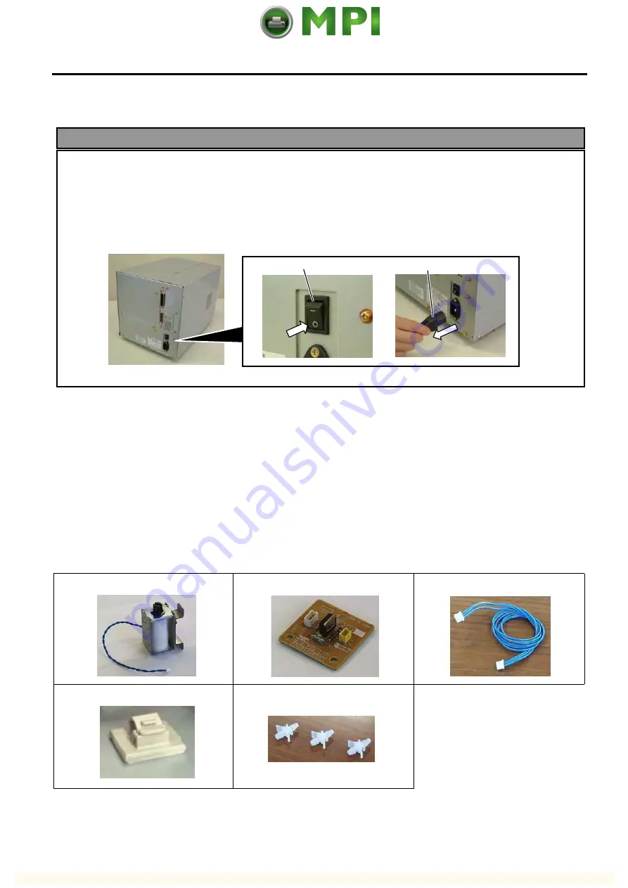
2.  Turn the power OFF and disconnect the power cord before installing the ribbon saving module.  


3.  Be careful not to pinch your fingers or hands with the covers. 


4.15  RIBBON SAVING MODULE (B-9904-R2-QM-R)


NOTE:  The B-9904-R2-QM Ribbon Saving Module is available only with Firmware V1.2A or later.  Please 

be careful that the earlier firmware version does not support it. 


4.15.1 Applicable Model 

This optional device is the ribbon saving module, which is intended for the following models: 

B-SX4T-QM-R Series 


4.15.2 Packing List 

All the following parts are supplied with the kit.  Make sure you have all items shown below. 

Solenoid (1 pc.) 

RSV PC Board (1 pc.) 

Solenoid Harness (1 pc.) 

Cable Clamp (1 pc.) 

Locking Support (3 pcs.) 
 

• 

Installation Manual (1 copy) 

• 

SM-4x8 Screw (2 pcs.) 


WARNING! 


Power Switch 

Power Cord 

Mantenimiento Periféricos Informáticos C/Canteras,15 28860 Paracuellos de Jarama Madrid Tel: 91 748 16 04 www.mpi.com.es

Summary of Contents for TEC B-SX4T Series

Page 1: ...rinter B SX4T SX5T SERIES Document No EO18 33012B Original Jan 2003 Revised Feb 2003 Jan 2006 Maintenance Manual Mantenimiento Periféricos Informáticos C Canteras 15 28860 Paracuellos de Jarama Madrid Tel 91 748 16 04 www mpi com es ...

Page 2: ...to follow manual instructions or any unauthorized modification substitution or change to this product will void the limited product warranty WARNING Follow all manual instructions Failure to do so could create safety hazards such as fire or electrocution Mantenimiento Periféricos Informáticos C Canteras 15 28860 Paracuellos de Jarama Madrid Tel 91 748 16 04 www mpi com es ...

Page 3: ...0 RFID MODULE B 9704 RFID U1 US EU EU R 4 43 4 10 1 Applicable Model 4 43 4 10 2 Packing List 4 43 4 10 3 Removing the Platen Frame Top and Attaching the Ribbon Guide 4 45 4 10 4 Attaching the Antenna 4 48 4 10 5 Attaching the RFID Module 4 51 4 10 6 Parameter Setting and Operation Check for the RFID Module 4 54 4 11 RFID MODULE B 9704 RFID H1 QM QM R 4 56 4 11 1 Applicable Model 4 56 4 11 2 Packi...

Page 4: ...stallation Procedure 4 118 4 20 FANFOLD PAPER GUIDE MODULE B 4905 FF QM R 4 121 4 20 1 Applicable Model 4 121 4 20 2 Packing List 4 121 4 20 3 Installation Procedure 4 121 4 21 WIRELESS LAN MODULE B 9700 WLAN QM R 4 122 4 21 1 Applicable Model 4 122 4 21 2 Packing List 4 122 4 21 3 Installation Procedure 4 123 4 22 RFID MODULE B SX704 RFID U2 EU R 4 127 4 22 1 Applicable Model 4 128 4 22 2 Packing...

Page 5: ...rward Wait Selection 5 25 5 4 10 Forward Backward Feed Action Selection 5 26 5 4 11 Head Up Cut Rewinder Selection 5 26 5 4 12 Solenoid Type Selection 5 27 5 4 13 Ribbon Saving Function Selection 5 27 5 4 14 Control Code Selection 5 28 5 4 15 Strip Wait Status Selection 5 29 5 4 16 FEED Key Function Selection 5 29 5 4 17 KANJI Code Selection 5 30 5 4 18 EURO Code Selection 5 30 5 4 19 Auto Print H...

Page 6: ...ibbon End Sensor Adjustment 5 62 5 8 RAM CLEAR 5 63 5 8 1 RAM Clear Menu Selection 5 63 5 8 2 No RAM Clear 5 64 5 8 3 Maintenance Counter Clear 5 64 5 8 4 Printer Parameter Clear 5 64 5 9 IP ADDRESS SETTING 5 67 5 10 BASIC SETTING 5 70 5 10 1 Basic Specification Selection Mode 5 70 5 10 2 Basic File Browser 5 71 5 10 3 Basic Trace Selection Mode 5 71 5 10 4 Basic Expansion Mode 5 71 5 11 RFID Modu...

Page 7: ... PC BOARD 10 5 10 3 PANEL PC BOARD AND LCD UNIT 10 13 10 3 1 LCD 10 13 10 3 2 Panel PC Board 10 14 10 4 STEPPING MOTOR 10 15 10 5 RIBBON MOTORS TAKE UP FEED 10 17 10 5 1 Ribbon Motor Take up 10 17 10 5 2 Ribbon Motor Feed 10 19 10 6 RIBBON MOTOR SENSORS TAKE UP FEED 10 21 10 6 1 Ribbon Motor Sensor Take up 10 21 10 6 2 Ribbon Motor Sensor Feed 10 23 10 7 PRINT HEAD 10 25 10 8 PLATEN 10 29 10 9 FEE...

Page 8: ...PORATION All Rights Reserved 570 Ohito Izunokuni shi Shizuoka ken JAPAN This manual is intended for both B SX4T series and B SX5T series Please note that the illustrations and pictures provided are of the B SX4T series The SP40II has been developed from the B SX4T GS10 QP and the differences between two are the color of the front cover and the operation panel ass y the model name label and the CD ...

Page 9: ...SX5T series with the serial number of 3Wxxxxxx or later 1 1 PROCEDURE 1 Open the carton 2 Unpack the accessories and the front pad from the carton 3 Unpack the pads and the printer from the carton 4 Remove the four pieces of tape and the rear pad from the printer Carton Accessories Front Pad Printer Bottom Pad Right Side Pad Left Side Pad Tape Rear Pad Tape Tape Mantenimiento Periféricos Informáti...

Page 10: ...ide plate and two SMW 3x8 screws from the printer inside Also remove the tape from the rewinder unit in the printer NOTE For the installation procedure of the rewinder guide plate refer to Section 4 3 Ribbon Shaft Holder Plate Ribbon Shaft Pad Top Cover Tape Tape Tape Tape OPEN Rewinder Guide Plate SMW 4x8 Screw Rewinder Tape Mantenimiento Periféricos Informáticos C Canteras 15 28860 Paracuellos d...

Page 11: ... number of 3Wxxxxxx or later 2 PRINTER INSTALLATION 1 Place the printer on the level surface 2 Keep the slit free or the printer will be overheated Also keep enough space for replacing and maintenance works while the top cover is opened Left Side Cover Top Cover Slit QC Card QQ model only Warranty Registration QQ model only Fan Filter Power Cord CD ROM Ferrite Core B SX5T series only Cable Band B ...

Page 12: ...t head and the inner parts of the printer being hot 3 When cleaning the cutter be careful not to be injured by the cutter blade B 8204 QM B 4205 QM 4 Be careful not to pinch your fingers or hands with the covers CAUTION 1 Fix the harnesses and the cord bushes with the cable clamp Failure to do this may cause the covers to catch them Cutter Blade Cutter Blade Sensor Harness Sensor Harness Print Hea...

Page 13: ...inting 4 When replacing parts or performing maintenance on the printer be careful not to damage the print head with a hard object like a watch or a ring Since the print head element can be easily damaged by shock please treat it carefully by not hitting a hard object against it Printer Block Screw Sensor Window Care must be taken not to allow the metal or glass part of a watch to touch the print h...

Page 14: ...Open the top cover and remove the three SMW 4x8 screws that secure the side panel L 3 Close the top cover 4 Lift the side panel L and put it aside 5 In case of non RFID ready printers release the fan motor harness from the cable clamp disconnect it from CN19 on the Main PC board and then separate the side panel L Open Position Close Position B 4x5 Screw B 4x5 Screw SMW 4x8 Screw Side Panel L Fan M...

Page 15: ...rclockwise to Free position 3 Open the ribbon shaft holder plate 4 Raise the print head block until it stops NOTE DO NOT excessively push down the print head block to close it Dosing so may cause a failure of the print head block or damage to the print head Side Panel L Fan Motor Harness Fan Motor CN19 Main PC Board Ribbon Shaft Holder Plate Head Lever Free position Lock position Label Lock positi...

Page 16: ...emove the SMW 4x8 screw that secures the operation panel ass y 4 Fully open the top cover otherwise the operation panel ass y is stuck on the tab and cannot be removed from the printer 5 Lift the operation panel ass y to release the hook and then remove the operation panel ass y by moving it forward SMW 4x8 Screw Top Cover Operation Panel Ass y Tab Mantenimiento Periféricos Informáticos C Canteras...

Page 17: ...he operation panel ass y 7 Reassemble in the reverse order of removal Lead the operation panel harness through the bush so that the side panel L does not catch it Operation Panel Ass y Operation Panel Harness Hook Bottom Plate Bush Operation Panel Harness Mantenimiento Periféricos Informáticos C Canteras 15 28860 Paracuellos de Jarama Madrid Tel 91 748 16 04 www mpi com es ...

Page 18: ...rface Board B 9704 RFID U1 US EU RFID Module B 9704 RFID H1 QM RFID Module In this section installation procedures for these optional equipments are described NOTES 1 The B 4205 QM B 8204 QM and B 9904 H QM cannot be used together 2 The B 9700 LAN QM and the B 9700 USB QM cannot be used together 3 When using the B 9700 PCM QM together with the B 9700 LAN QM or the B 9700 USB QM attach the B 9700 P...

Page 19: ... Remove the side panel L Refer to Section 3 2 4 Remove the operation panel ass y Refer to Section 3 4 5 Open the print head block Refer to Section 3 3 6 Remove the two SMW 4x8 screws that secure the strip sensors TR and LED 7 Release the strip sensor LED harness from the cable clamp and disconnect it from the shorter harness of the strip sensor harness TR Black Screws SMW 4x8 SMW 4x8 Rewinder Guid...

Page 20: ...ss and the longer harness of the rewind full sensor TR to the space under the Main PC board with the cable clamp so that they are not pinched by the covers or printer s internal components 11 Reassemble the operation panel ass y and the expansion I O board in the reverse order of removal 6 When using the rotary cutter on the B SX4T series the print speed of 10 sec is not supported Also when using ...

Page 21: ...tall the RFID module prior to the cutter All the following parts are supplied with the kit Make sure you have all items shown below Cutter Unit 1 pc Cutter Cover 1 pc Cutter Harness 1 pc Print Head Cleaner 1 pc P No FMQB0051601 Cutter Attachment Screw 2 pcs Bush 1 pc Installation manual 1 copy FL 4x6 Screw 1 pc 1 Remove the two black screws to detach the front plate NOTE Retain the two black screw...

Page 22: ...he FL 4x6 screw 6 Connect the cutter harness to CN1 on the cutter I F PC board 7 Fit the bush to the cutter harness in the orientation shown below 8 Insert the cutter harness into the gap between the cutter unit and the printer and then into the hole in the main frame Fit the bush into the hole Cutter Attachment Screw FL 4x6 Screw Cutter Unit CN1 Cutter Harness Cutter I F PC Board Bush Cutter Harn...

Page 23: ...n the Main PC Board 11 Fit the cutter cover on the cutter attachment screws and fix it to the cutter unit with the two cutter screws NOTE Be careful not to pinch the cutter harness by the cutter cover 12 Reassemble the side panel L and close the top cover Finally check the cutter operation NOTE For cleaning the cutter refer to section 8 CN15 Main PC Board Cutter Harness Cutter Screw Cutter Attachm...

Page 24: ...anual 1 copy SM 4x8 Screw 6 pcs NOTES 1 When using the rotary cutter on the B SX4T series the print speed of 10 sec is not supported Also when using the rotary cutter be sure to install the ribbon saving module B 9904 R QM Failure to do this may cause a paper jam or ribbon error For the installation procedure please refer to Section 4 9 2 The B 8204 QM with the serial number of 2805Dxxxxxx or earl...

Page 25: ...tter PC Board fix it to the Rotary Cutter Frames A and B with three SMW 3x6 screws Then attach the Rotary Cutter PC Board Cover with an SMW 3x6 screw SMW 3x6 SMW 4x8 Rotary Cutter Guide Plate B Rotary Cutter Guide Plate C Rotary Cutter PC Board Cover To be used later SMW 4x8 Rotary Cutter Frame B P No 7FM01068000 Rotary Cutter Frame A P No 7FM0167000 Determine the position by fitting the two parts...

Page 26: ...he cutter unit to detach the cutter paper guide C 2 Secure the B SX cutter paper guide C with the M 4x6 set screws while pushing it upward CAUTION Do not hold the cutter paper guides when attaching the Cutter Unit to the printer Doing so may deform the cutter paper guides causing a paper jam Cutter Paper Guide C M 4x6 M 4x6 B SX Cutter Paper Guide C Cutter Paper Guide DO NOT Mantenimiento Periféri...

Page 27: ...ix the cutter drive unit to the printer with the three SM 4x8 screws 5 Connect the 9 pin connector of the harness ass y to CN7 and 2 pin connector to CN9 on the cutter driver unit respectively 6 Fit the bush to the harness ass y in the orientation as shown below SM 4x8 Screw Cutter Drive Unit SM 4x8 Screw CN7 9 pins CN9 2 pins Harness Ass y Bush Harness Ass y Mantenimiento Periféricos Informáticos...

Page 28: ... to CN18 on the Main PC board respectively 9 Open the print head block Refer to section 3 3 10 Connect the four harnesses of the cutter unit to CN8 CN10 CN11 and CN12 on the cutter drive unit Main PC Board CN18 2 pins CN15 9 pins Harness Ass y Hole Main Frame Harness Ass y Cutter Unit Cutter Drive Unit Print Head Block CN8 CN12 CN10 CN11 Mantenimiento Periféricos Informáticos C Canteras 15 28860 P...

Page 29: ...e that the anti static brush is protruding from the media outlet 13 Close the print head block and ribbon shaft holder plate NOTE DO NOT excessively push down the print head block to close it Doing so may cause a failure of the print head block or damage to the print head 14 Reassemble the side panel L and close the top cover Finally check the cutter operation Cutter Unit Notch Tab SM 4 x 8 Screw ...

Page 30: ...RFID module prior to the strip module NOTE The strip module is standard on the B SX5T series All the following parts are supplied with the kit Make sure you have all items shown below Rewinder Ass y 1 pc Rewinder Guide Plate 1 pc Bush 1 pc Strip Sensor TR 1 pc Strip Sensor LED 1 pc Rewind Paper Guide 1 pc Installation Manual 1 copy SM 4x8B Screw 10 pcs SM 3x6B Screw 1 pc SM 4x8C Screw 1 pc Manteni...

Page 31: ...ss y from the printer Refer to section 3 4 5 Attach the rewind paper guide to the base with the two M 4x8 screws 6 Align the notch of the take up holder with the screw hole of the rewinder ass y and attach them to the printer with the four SM 4x8B screws and the SM 4x8C screw 7 Attach the rewind full sensor LED to the base with the SM 3x6B screw Screw Hole Rewind Paper Guide M 4x8 Screw Mantenimie...

Page 32: ...e rewind full sensor Tr into the hole in the printer frame Fit the bush into the hole SM 4x8B Screw SM 4x8C Screw SM 4x8B Screw Take up Holder Notch Rewind Full Sensor LED SM 3x6B Screw Rewinder Ass y Base Bush Longer Harness of the Rewind Full Sensor Tr Longer Harness of the Rewind Full Sensor Tr Bush Hole Frame Rewinder Harness Mantenimiento Periféricos Informáticos C Canteras 15 28860 Paracuell...

Page 33: ...Otherwise it may be difficult to pull out the wound backing paper roll When using a paper core put the core on the Take up Spool with the Holder Stopper on it and Attach the top edge of the backing paper to the core with adhesive tape The Take up Clip is not necessary This winding method is applicable to the Built in Rewinder mode 11 Open the print head block Refer to section 3 3 12 Fix the longer...

Page 34: ...he cut and the bush reassemble the operation panel ass y to the printer Then pass the strip sensor harness over the tab on the back of the operation panel ass y NOTE Be careful not to pinch the strip sensor harnesses by the operation panel SM 4x8B Screw Strip Sensor Tr Strip Sensor Harness for LED Shorter Harness of the Strip Sensor Harness for Tr Strip Sensor LED SM 4x8B Screw Tab Strip Sensor Tr...

Page 35: ...failure of the print head block or damage to the print head 19 When using the printer in batch mode or strip mode attach the front plate removed in step 1 20 When using the printer in built in rewinder mode attach the rewinder guide plate to the front of the printer with the two SMW 4x8 screws 21 Make a test print to check for proper strip issue NOTE If the label skews refer to section 8 Cable Cla...

Page 36: ... 2 pcs NOTES 1 The B 9904 R2 QM Ribbon Saving Module is available only with Firmware V1 2A or greater Please be careful that the earlier firmware version does not support it 2 The insulation tape of the solenoid of the B 9904 R QM is blue and that of the B 9904 R2 QM is black 1 Remove the side panel L from the printer Refer to section 3 2 2 Remove the operation panel ass y from the printer Refer t...

Page 37: ... folded tag paper 1 5 mm thick between the print head and the platen and then turn the head lever to Lock position Insert the head up arm into the plunger of the solenoid While holding down the head up arm slightly lift the solenoid Secure the solenoid to the frame with the two SM 4x8 screws keeping the solenoid in contact with the spacer Frame SM 4x8 Screw Head Up Arm Plunger Solenoid Spacer RSV ...

Page 38: ...e RSV PC board and CN11 on the Main PC board Pass the solenoid harness through the cut 8 Connect the solenoid cable to CN2 on the RSV PC board 9 After attaching the solenoid reassemble the operation panel ass y and the side panel L in the reverse order of removal CN2 CN1 Solenoid Cable CN11 Main PC Board Solenoid Harness RSV PC Board Cut Cable Clamp Solenoid Cable Solenoid Solenoid Harness Manteni...

Page 39: ... PCMCIA interface board first NOTE When both B 9700 PCM QM and B 9700 LAN QM are installed inserting a LAN PC card into the slot of the B 9700 PCM QM disables the B 9700 LAN QM All the following parts are supplied with the kit Make sure you have all items shown below PCMCIA Interface Board 1 pc 1 Remove the side panel L from the printer Refer to section 3 2 2 Loosen the two M 3x5 screws of the PCM...

Page 40: ...e from CN1 on the Expansion I O board 2 Remove the two B 3x6 screws to detach the Expansion I O board from the printer 4 Firmly connect CN101 on the PCMCIA interface board directly to CN7 on the Main PC board 5 Secure the PCMCIA interface board to the rear plate with the two SM 3x6 screws PCMCIA Interface Board Main PC Board CN101 CN7 SM 3x6 Screw Rear Plate Rear Plate B 3x6 Screw Expansion I O Bo...

Page 41: ...r USB interface board is also installed go to the next step NOTE Keep the two SM 3x6 screws and blind plate A safe when the LAN interface board or USB interface board is installed 8 Reassemble the side panel L in the reverse order of removal If the Expansion I O board was removed at the beginning reassemble it NOTE For insertion removal and handling of the PC card refer to the Owner s Manual Blind...

Page 42: ...the following parts are supplied with the kit Make sure you have all items shown below USB Interface Board 1pc PCB Attachment Plate 1 pc NOTE When using the PCMCIA interface board B 9700 PCM QM together the PCB attachment plate will be used 1 Turn the power off and disconnect the power cord 2 Loosen the two M 3x5 screws of the USB interface board Refer to Caution above 3 Remove the side panel L fr...

Page 43: ...go to the next step 6 Firmly connect CN50 connector on the USB interface board directly to CN7 on the Main PC board or CN1 on the PCMCIA interface board When connecting to the Main PC Board When connecting the PCMCIA Interface Board PCMCIA Interface Board PCB Attachment Plate SM 3x6 Screw USB Interface Board Main PC Board CN50 CN7 USB Interface Board PCMCIA Interface Board CN50 CN1 Mantenimiento P...

Page 44: ...ing to the Main PC board or PCB attachment plate when connecting to the PCMCIA interface board with the SM 3x6 screw When connecting to the Main PC Board When connecting to the PCMCIA Interface Board SM 3x6 Screw USB Interface Board SM 3x6 Screw USB Interface Board When connecting to the Main PC Board M 3x5 Screw SM 3x6 Screw PCB Support Plate When connecting to the PCMCIA Interface Board M 3x5 Sc...

Page 45: ...ce board has been installed go to the next step NOTE In case that the PCMCIA interface board has been installed retain the blind plate A 11 Reassemble the side panel L to the printer in the reverse order of removal Blind Plate A SM 3x6 Screw Rear Plate Mantenimiento Periféricos Informáticos C Canteras 15 28860 Paracuellos de Jarama Madrid Tel 91 748 16 04 www mpi com es ...

Page 46: ...he slot of the B 9700 PCM QM disables the B 9700 LAN QM All the following parts are supplied with the kit Make sure you have all items shown below LAN Interface Board 1pc PCB Attachment Plate NOTE When using the PCMCIA interface board B 9700 PCM QM together the PCB attachment plate will be used M 3x5 Screw License Agreement Please be sure to read the License Agreement before opening the sealed LAN...

Page 47: ...the back NOTE Keep the blind plate A safe as this will be necessary when the machine is modified to the standard type 4 If the PCMCIA interface board is also installed attach the PCB attachment plate to the plate to which the PCMCIA interface board is secured with the SM 3x6 screw If not go to the next step Blind Plate A SM 3x6 Screw PCB Attachment Plate SM 3x6 Screw PCMCIA Interface Board Manteni...

Page 48: ... two SM 3x6 screws When connecting to the Main PC Board When connecting to the PCMCIA Interface Board LAN Interface Board MAIN PC Board CN50 CN7 LAN Interface Board PCMCIA Interface Board CN50 CN1 When connecting to the Main PC Board When connecting to the PCMCIA Interface Board SM 3x6 Screw SM 3x6 Screw Rear Plate Rear Plate LAN Interface Board LAN Interface Board Mantenimiento Periféricos Inform...

Page 49: ...ide panel L in the reverse order of removal NOTE Precaution for the LAN cable connection When connecting a LAN cable with the hooded connectors to the LAN interface board it may not be connected depending on the shape of the hood In this case move aside the hood connect the cable and return the hood to the former position When connecting to the Main PC Board M 3x5 Screw SM 3x6 Screw PCB Support Pl...

Page 50: ...tems shown below Expansion I O Board 1 pc Expansion I O Cable 1 pc Installation Manual 1 copy Locking Support WLS 16 0 1 pc NOTE The locking support is not used on this printer 1 Turn the power off and disconnect the power cord 2 Remove the side panel L from the printer Refer to section 3 2 3 Remove the two M 3x6 screws and detach the blind plate B from the back 4 Remove the two B 3x6 screws from ...

Page 51: ...oved in Step 4 7 Connect the expansion I O cable to CN1 on the expansion I O board 8 Reassemble the side panel L in the reverse order of removal 9 Perform a loop back check to confirm that the expansion I O board functions properly Expansion I O Cable CN3 Main PC Board CN1 Expansion I O Board Expansion I O Cable B 3x6 Screw Rear Plate Mantenimiento Periféricos Informáticos C Canteras 15 28860 Para...

Page 52: ...s Installation Manual 1 copy SM 4x8 Screw 2 pcs NOTES 1 The B 9904 R2 QM Ribbon Saving Module is available only with Firmware V1 2A or greater Please be careful that the earlier firmware version does not support it 2 The insulation tape of the solenoid of the B 9904 R QM is blue and that of the B 9904 R2 QM is black Rotary Cutter All the following parts are supplied with the kit Make sure you have...

Page 53: ... the enclosed B SX cutter paper guide C using the following procedure 1 Remove the two M 4x6 Set Screws from the cutter unit to detach the cutter paper guide C CAUTION Do not hold the cutter paper guides when attaching the Cutter Unit to the printer Doing so may deform the cutter paper guides causing a paper jam Cutter Paper Guide C M 4x6 Cutter Paper Guide NG Cutter Blade Mantenimiento Periférico...

Page 54: ...n 3 4 3 Fit the three locking supports into the RSV PC board 4 Secure the RSV PC board to the printer with the locking supports NOTE Do not push the center of the RSV PC board when attaching it to the printer Doing so may break the PC board Hold the locking supports and push them into the holes for securing the RSV PC board M 4x6 B SX Cutter Paper Guide C RSV PC Board Locking Support RSV PC Board ...

Page 55: ... the head up arm slightly lift the solenoid Secure the solenoid to the frame with the two SM 4x8 screws keeping the solenoid in contact with the spacer 6 Attach the cable clamp to the frame of the printer Fix the solenoid cable with this cable clamp NOTE Be careful not to snag the solenoid harness when running it Frame SM 4x8 Screw Head Up Arm Plunger Solenoid Spacer Cable Clamp Solenoid Cable Sol...

Page 56: ...oid cable to CN2 on the RSV PC board 9 Attach the operation panel ass y to the ptinter 10 Remove the two black screws to detach the front plate Refer to section 4 1 11 Fix the cutter drive unit to the printer with the three SM 4x8 screws CN2 CN1 Solenoid Cable CN11 Main PC Board Solenoid Harness RSV PC Board Cut SM 4x8 Screw Cutter Drive Unit SM 4x8 Screw Mantenimiento Periféricos Informáticos C C...

Page 57: ...o CN9 on the cutter driver unit respectively 13 Fit the bush to the harness ass y in the orientation as shown below 14 Insert the harness ass y into the hole in the main frame Fit the bush into the hole CN7 9 pins CN9 2 pins Harness Ass y Bush Harness Ass y Hole Main Frame Harness Ass y Mantenimiento Periféricos Informáticos C Canteras 15 28860 Paracuellos de Jarama Madrid Tel 91 748 16 04 www mpi...

Page 58: ...the Main PC board respectively 16 Open the print head block Refer to section 3 3 17 Connect the four harnesses of the cutter unit to CN8 CN10 CN11 and CN12 on the cutter drive unit Main PC Board CN18 2 pins CN15 9 pins Harness Ass y Cutter Unit Cutter Drive Unit Print Head Block CN8 CN12 CN10 CN11 Mantenimiento Periféricos Informáticos C Canteras 15 28860 Paracuellos de Jarama Madrid Tel 91 748 16...

Page 59: ...ure that the anti static brush is protruding from the media outlet 20 Close the print head block and ribbon shaft holder plate NOTE DO NOT excessively push down the print head block to close it Doing so may cause a failure of the print head block or damage to the print head 21 Reassemble the side panel L and close the top cover Finally check the cutter operation and ribbon saving operation Cutter ...

Page 60: ...trip sensors Tr and LED before installing the RFID module The strip module is standard feature of the B SX5T series 4 10 1 Applicable Model The B 9704 RFID U1 US EU model is intended for the following models B SX4T GS10 QQ QQ US QP RFID Ready printer Serial No 2604Wxxxxxx or later B SX5T TS10 QQ QQ US QP RFID Ready printer Serial No 2604Wxxxxxx or later The B 9704 RFID H1 QM R model is intended fo...

Page 61: ...ouble Sems Screw EU 6 pc US 0 pc US 2 pc SMW 3x6 Double Sems Screw Small Washer Type Spare EU 2 pc PT 3x6 P TITE Screw Spare EU 0 pc US 1 pc US 1 pc RFID Module Cover EU 1 pc FCC Sticker US model EU 0 pc US 0 pc CE Sticker EU model EU 1 pc NOTE Double Sems Screws SMW 3x6 and P TITE Screws PT 3x6 are supplied just in case that the antenna attachment position is changed Mantenimiento Periféricos Inf...

Page 62: ... 9904 H QM strip module has been installed or in case of the B SX5T remove the rewinder guide plate and strip sensors before installing an RFID module 1 Remove the two black screws to detach the front plate Refer to section 4 1 2 Remove the side panel L from the printer Refer to section 3 2 3 Push the Hook through the rectangle hole with a jeweler s screw driver or something and remove the Platen ...

Page 63: ...tly pull the Head Side Plate and remove the two Ribbon Guide Shafts NOTE One of the removed Ribbon Guide Shafts and SMW 2 6x6 Screws are re used when attaching the Ribbon Guide Keep the unused ones for future use Platen Frame Top SMW 3x6 Screw SMW 4x8 Screw SMW 2 6x6 Screw Ribbon Guide Shaft Head Side Plate SMW 4x8 Screw SMW 3x6 Screw Mantenimiento Periféricos Informáticos C Canteras 15 28860 Para...

Page 64: ... Head Side Plate to the Print Head Block with the SMW 3x6 Screw and the SMW 4x8 Screw Be sure to fit the locating pins provided on the other side of the Ribbon Guide into the locating holes of the Print Head Block 11 Close the Ribbon Shaft Holder Plate and tighten the two screws which were temporarily tightened in Step 14 while holding down the Print Head Block Ribbon Guide Ribbon Guide s D cut Ri...

Page 65: ...nto the printer as shown below Let the protruding screw of the printer pass through the slit of the Antenna Frame 2 Secure the Antenna Frame with the three screws removed in Step 10 of Section 3 1 3 Mount the Antenna Cover on the inside of the Antenna Frame Be sure to fit the locating pins of the Antenna Cover into the oval holes and the cuts in the Antenna Frame Antenna Frame including Antenna Sc...

Page 66: ... Head Block and slide the Antenna Frame into the printer as shown below Let the protruding screw of the printer pass through the slit of the Antenna Frame 2 Secure the Antenna Frame with the three screws removed in Step 10 of Section 3 1 Antenna Cover SMW 3x6 Screw Antenna Frame Slit Screw SMW 3x6 Screw SMW 4x8 Screw Mantenimiento Periféricos Informáticos C Canteras 15 28860 Paracuellos de Jarama ...

Page 67: ...e Antenna Frame NOTE Pass the Antenna Cable between the Antenna Frame and the Media Sensor as shown in the picture below 4 Push the Antenna Cover containing the Antenna backward and secure it with the two SMW 3x6 screws Locating Pin Locating Pin Cut Oval Hole Antenna Cover including Antenna Antenna Frame Antenna Frame Antenna Cable Media Sensor Antenna Cover including Antenna SMW 3x6 Screw Manteni...

Page 68: ...ble Clamp 3 Attach the RFID Module to the RFID Attachment Plate A and the RFID Attachment Plate B with the three SMW 3x6 screws NOTE Care should be taken not to catch the cables between the RFID Module and the RFID Attachment Plate A Bush Cable Clamp Bush Cable Clamp Antenna Cable RFID Attachment Plate B RFID Module RFID Attachment Plate A SMW 3x6 Screw SMW 3x6 Screw Cable RFID Module RFID Attachm...

Page 69: ...e 5 Connect the Antenna Cable to the RFID Module until it clicks To prevent the Antenna Cable from being caught in the Side Panel L or Fan Motor fold the cable and fix it with the two Cable Clamps CN14 CN1 RFID Module Interface Cable Main PC Board Cable Clamp RFID Mod ule Antenna Cable Antenna Cable Mantenimiento Periféricos Informáticos C Canteras 15 28860 Paracuellos de Jarama Madrid Tel 91 748 ...

Page 70: ...the Antenna Cable 7 Attach the Side Cover L the Front Plate the Platen Holder Cover the Platen and the Strip Plate in the reverse order of removal Refer to Section 4 to program the RFID Module and perform an operation check NOTE When attaching the Side Cover L carefully lead the Fan Motor Harness so that it does not get sucked into the Fan Motor Tab RFID Module RFID Module Cover Slot Pass the Inte...

Page 71: ...tep 2 When the program version is V4 1 or greater US EU model or V4 4 or greater EU R model go to Step 3 2 When the program version is V3 1 or older upgrade it to V3 2 or greater in the following order Please obtain the latest firmware from http barcode toshibatec co jp Ris products barcode support en contents software index html 1 Print the Maintenance Counter Parameter Setting to keep the record...

Page 72: ... 5 12 NOTE Available RFID tags EPC Class 0 Read only EPC Class 1 EPC Class 1 Gen2 Only when the RFID module supports Gen2 ISO 18000 6B WEP KEY 3 101112131415161718191A1B1C WEP KEY 4 202122232425262728292A2B2C RFID MODULE U1 RFID TAG TYPE EPC CI Gen2 RFID ERR CHECK OFF RFID RETRY 3 RFID RD CYCLE 5 4 0sec RFID WT CYCLE 5 2 0sec RFID ADJ RETRY 00mm RFID POWER LEV 50 Parameters for the RFID Module Ini...

Page 73: ...stalling the RFID module The strip module is standard feature of the B SX5T series 4 11 1 Applicable Model This optional device is intended for the following models The B 9704 RFID H1 QM model is intended for the following models B SX4T GS10 QQ QQ US QP RFID Ready printer Serial No 2604Wxxxxxx or later B SX5T TS10 QQ QQ US QP RFID Ready printer Serial No 2604Wxxxxxx or later The B 9704 RFID H1 QM ...

Page 74: ...r 2 pcs NOTE To install the B 9704 RFID H1 QM in the printer TAGSYS RFID Module MEDIOTM S002 and the exclusive antenna are required separately Before installation solder the supplied Interface Cable to the RFID module as shown in the picture below and attach the RFID Module and the Antenna to the RFID Plate and the Antenna Cover respectively RFID Module Antenna Interface Cable Mantenimiento Perifé...

Page 75: ...rown Red Orange Black 5 CTS Black 6 DTR Black 7 DSR Black 8 GND Yellow 30 5mm 120mm 10mm 5 2mm Connector DF3 8S 2C HIROSE ELECTRIC CO LTD Terminal DF3 2428SCF HIROSE ELECTRIC CO LTD Pin No Signal Color 1 2 3 4 VCC TXD RXD RTS Brown Red Orange Black 5 CTS Black 6 DTR Black 7 DSR Black 8 GND Yellow Mantenimiento Periféricos Informáticos C Canteras 15 28860 Paracuellos de Jarama Madrid Tel 91 748 16 ...

Page 76: ...in the printer the pattern side of the Antenna faces up and the Antenna Cable is positioned at the printer frame side 4 11 4 Attaching the RFID Module to the RFID Plate 1 Put the Nylon Washer onto the SMW 2x10 Screw Do the same to the other SMW 2x10 Screw 2 Place the RFID Module on the RFID Plate as shown in the picture below Insert the Spacers under the RFID Module and secure it to the RFID Plate...

Page 77: ...rectangle hole with a jeweler s screw driver or something and remove the Platen Holder Cover in the direction indicated by the arrow 4 Lift the right side of the Strip Plate and then pull and remove it 5 Remove the Platen and the Platen Holder in steps 1 to 3 as shown below Strip Plate Hook 1 2 2 1 Platen Platen Holder 1 2 3 Push Platen Holder Cover Mantenimiento Periféricos Informáticos C Cantera...

Page 78: ...y pull the Head Side Plate and remove the two Ribbon Guide Shafts NOTE One of the removed Ribbon Guide Shafts and SMW 2 6x6 Screws are re used when attaching the Ribbon Guide Keep the unused ones for future use Platen Frame Top SMW 3x6 Screw SMW 4x8 Screw SMW 2 6x6 Screw Ribbon Guide Shaft Head Side Plate SMW 4x8 Screw SMW 3x6 Screw Mantenimiento Periféricos Informáticos C Canteras 15 28860 Paracu...

Page 79: ...e Head Side Plate to the Print Head Block with the SMW 3x6 Screw and the SMW 4x8 Screw Be sure to fit the locating pins provided on the other side of the Ribbon Guide into the locating holes of the Print Head Block 11 Close the Ribbon Shaft Holder Plate and tighten the two screws which were temporarily tightened in Step 14 while holding down the Print Head Block Ribbon Guide Ribbon Guide s D cut R...

Page 80: ...e Antenna Frame with the three screws removed in Step 10 of Section 3 1 3 Mount the Antenna Cover containing the Antenna on the inside of the Antenna Frame Be sure to fit the locating pins of the Antenna Cover into the oval holes and the cuts in the Antenna Frame Antenna Frame SMW 3x6 Screw Locating Pin Locating Pin Cut Oval Hole Antenna Cover including Antenna Antenna Frame Screw Slit SMW 4x8 Scr...

Page 81: ...Antenna Frame and the Media Sensor as shown in the picture below 4 Push the Antenna Cover backward and secure it with the two SMW 3x6 screws Antenna Cover including Antenna SMW 3x6 Screw Antenna Frame Media Sensor Antenna Cable Mantenimiento Periféricos Informáticos C Canteras 15 28860 Paracuellos de Jarama Madrid Tel 91 748 16 04 www mpi com es ...

Page 82: ...the RFID Module to the RFID Attachment Plate A and the RFID Attachment Plate B with the three SMW 3x6 screws NOTE Care should be taken not to catch the cables between the RFID Module and the RFID Attachment Plate A Bush Cable Clamp Bush Cable Clamp Antenna Cable RFID Attachment Plate B RFID Module RFID Attachment Plate A SMW 3x6 Screw SMW 3x6 Screw Cable RFID Module Mantenimiento Periféricos Infor...

Page 83: ...able Clamps 10 Attach the Side Cover L the Front Plate the Platen Holder Cover the Platen and the Strip Plate in the reverse order of removal Refer to Section 4 to program the RFID Module and perform an operation check NOTE When attaching the Side Cover L carefully lead the Fan Motor Harness so that it does not get sucked into the Fan Motor CN14 RFID Cable RFID Module Main PC Board Mark RFID Modul...

Page 84: ...connected 4 Change the parameter setting of the RFID tag type to a proper one 5 Print the Maintenance Counter Parameter Settings and the Self Diagnostic Test result to confirm the RFID Module status 5 If RFID NG No Good is printed check the cable connections and parameter settings related to the RFID Module again 6 Try a read and write of the RFID tag by using the RFID Analyze Tool When you do not...

Page 85: ...ect the power cord 2 Remove the two black screws to detach the front plate NOTE Retain the two black screws and front plate WARNING 1 Follow all manual instructions Failure to do so could create safety hazards such as fire or electrocution Manual instructions must be followed when installing option kits or adding cables to avoid system failures and to insure proper performance and operation Failur...

Page 86: ...the fan motor harness from CN19 on the Main PC board and then separate the side panel L 7 Turn the head lever clockwise to Free position 8 Open the ribbon shaft holder plate B 4x5 Screw P 4x8 Screw Top Cover B 4x5 Screw Side Panel L Ribbon Shaft Holder Plate Head Lever Lock position Tag Lock position Label Side Panel L Fan Motor Harness Fan Motor CN19 Main PC Board Mantenimiento Periféricos Inform...

Page 87: ...ent screws and the FL 4x6 screw 11 Connect the Cutter Harness to CN1 on the Cutter I F PC Board 12 Fit the bush to the cutter harness in the orientation shown below CN1 Cutter Harness Cutter I F PC Board Bush Cutter Harness Print Head Block Cutter Attachment Screw Cutter Unit FL 4x6 Screw Stopper Mantenimiento Periféricos Informáticos C Canteras 15 28860 Paracuellos de Jarama Madrid Tel 91 748 16 ...

Page 88: ...ad block or damage to the print head 15 Fix the cutter harness with the clamp and connect it to CN15 on the Main PC Board 16 Fit the cutter cover on the cutter attachment screws and fix it to the cutter unit with the two cutter screws NOTE Be careful not to pinch the cutter harness by the cutter cover 17 Reassemble the side panel L and close the top cover Finally check the cutter operation Hole Ma...

Page 89: ...wo black screws to detach the front plate NOTE Retain the two black screws and front plate When the printer is used in the built in rewinder mode Open the top cover remove the two SMW 4x8 screws and detach the rewinder guide plate from the printer 3 Remove the four B 4x5 screws from the side panel L 4 Open the top cover and remove the three P 4x8 screws that secure the side panel L Front Plate Bla...

Page 90: ...ecures the operation panel ass y 8 Half open the top cover otherwise the operation panel ass y cannot be removed from the printer 9 Lift the operation panel ass y to release the hook and then remove the operation panel ass y by moving it forward Operation Panel Ass y Top Cover SM 4x8 Screw Side Panel L Fan Motor Harness Fan Motor CN19 Main PC Board Mantenimiento Periféricos Informáticos C Canteras...

Page 91: ...tion panel ass y 11 Turn the head lever clockwise to Free position 12 Open the ribbon shaft holder plate Operation Panel Ass y Hook Ribbon Shaft Holder Plate Operation Panel Harness Head Lever Lock position Label Lock position Tag Mantenimiento Periféricos Informáticos C Canteras 15 28860 Paracuellos de Jarama Madrid Tel 91 748 16 04 www mpi com es ...

Page 92: ...e the strip sensor LED harness from the cable clamp and disconnect it from the shorter harness of the strip sensor harness TR Print Head Block Stopper SMW 4x8B Screw Strip Sensor Tr SMW 4x8B Screw Strip Sensor LED Cable Clamp Strip Sensor Harness for LED Shorter Harness of the Strip Sensor Harness for Tr Mantenimiento Periféricos Informáticos C Canteras 15 28860 Paracuellos de Jarama Madrid Tel 91...

Page 93: ...he strip sensor harness 18 Disconnect the longer harness of the rewind full sensor TR and rewinder harness from CN4 and CN15 on the Main PC board respectively NOTE Secure the rewinder harness and the longer harness of the rewind full sensor TR to the space under the Main PC board with the cable clamp so that they are not pinched by the covers or printer s internal components CN1 Expansion I O Boar...

Page 94: ... the Cutter Harness to CN1 on the Cutter I F PC Board 22 Fit the bush to the cutter harness in the orientation shown below 23 Insert the cutter harness into the gap between the cutter unit and the printer and then into the hole in the main frame Fit the bush into the hole Cutter Unit Hole Main Frame CN1 Cutter Harness Cutter I F PC Board Bush Cutter Harness Cutter Attachment Screw FL 4x6 Screw Man...

Page 95: ... the clamp and connect it to CN15 on the Main PC Board 26 Fit the cutter cover on the cutter attachment screws and fix it to the cutter unit with the two cutter screws NOTE Be careful not to pinch the cutter harness by the cutter cover 27 Reassemble the side panel L and close the top cover Finally check the cutter operation Clamp CN15 Main PC Board Cutter Harness Cutter Screw Cutter Attachment Scr...

Page 96: ...talling the Rotary Cutter Unit on the B SX4T Series 1 Turn the power off and disconnect the power cord 2 Remove the two black screws to detach the front plate NOTE Retain the two black screws and front plate WARNING 1 Follow all manual instructions Failure to do so could create safety hazards such as fire or electrocution Manual instructions must be followed when installing option kits or adding c...

Page 97: ... it aside 6 Disconnect the fan motor harness from CN19 on the Main PC board and then separate the side panel L 7 Fix the cutter drive unit to the printer with the three SM 4x8 screws B 4x5 Screw P 4x8 Screw Top Cover B 4x5 Screw Side Panel L SM 4x8 Screw Cutter Drive Unit Side Panel L Fan Motor Harness Fan Motor CN19 Main PC Board SM 4x8 Screw Mantenimiento Periféricos Informáticos C Canteras 15 2...

Page 98: ...tter driver unit respectively 9 Fit the bush to the harness ass y in the orientation as shown below 10 Insert the harness ass y into the hole in the main frame Fit the bush into the hole CN7 9 pins CN9 2 pins Harness Ass y Bush Harness Ass y Hole Main Frame Harness Ass y Mantenimiento Periféricos Informáticos C Canteras 15 28860 Paracuellos de Jarama Madrid Tel 91 748 16 04 www mpi com es ...

Page 99: ...wo black screws to detach the front plate NOTE Retain the two black screws and front plate When the printer is used in the built in rewinder mode Open the top cover remove the two SMW 4x8 screws and detach the rewinder guide plate from the printer 3 Remove the four B 4x5 screws from the side panel L 4 Open the top cover and remove the three P 4x8 screws that secure the side panel L Front Plate Bla...

Page 100: ...secures the operation panel ass y 8 Half open the top cover otherwise the operation panel ass y cannot be removed from the printer 9 Lift the operation panel ass y to release the hook and then remove the operation panel ass y by moving it forward Operation Panel Ass y Top Cover SM 4x8 Screw Side Panel L Fan Motor Harness Fan Motor CN19 Main PC Board Mantenimiento Periféricos Informáticos C Cantera...

Page 101: ...tion panel ass y 11 Turn the head lever clockwise to Free position 12 Open the ribbon shaft holder plate Operation Panel Ass y Ribbon Shaft Holder Plate Operation Panel Harness Hook Head Lever Lock position Label Lock position Tag Mantenimiento Periféricos Informáticos C Canteras 15 28860 Paracuellos de Jarama Madrid Tel 91 748 16 04 www mpi com es ...

Page 102: ...e the strip sensor LED harness from the cable clamp and disconnect it from the shorter harness of the strip sensor harness TR Print Head Block Stopper SMW 4x8B Screw Strip Sensor Tr SMW 4x8B Screw Strip Sensor LED Cable Clamp Strip Sensor Harness for LED Shorter Harness of the Strip Sensor Harness for Tr Mantenimiento Periféricos Informáticos C Canteras 15 28860 Paracuellos de Jarama Madrid Tel 91...

Page 103: ...rness of the rewind full sensor TR and rewinder harness from CN4 and CN15 on the Main PC board respectively NOTE Secure the rewinder harness and the longer harness of the rewind full sensor TR to the space under the Main PC board with the cable clamp so that they are not pinched by the covers or printer s internal components 19 Reassemble the operation panel ass y and the expansion I O board in th...

Page 104: ...o CN9 on the cutter driver unit respectively 22 Fit the bush to the harness ass y in the orientation as shown below 23 Insert the harness ass y into the hole in the main frame Fit the bush into the hole SM 4x8 Screw Cutter Drive Unit CN7 9 pins CN9 2 pins Harness Ass y Bush Harness Ass y Hole Main Frame Harness Ass y SM 4x8 Screw Mantenimiento Periféricos Informáticos C Canteras 15 28860 Paracuell...

Page 105: ...CN15 and 2 pin connector to CN18 on the Main PC board respectively 26 Connect the four harnesses of the cutter unit to CN8 CN10 CN11 and CN12 on the cutter drive unit Main PC Board Clamp Cutter Unit Cutter Drive Unit CN18 2 pins CN15 9 pins Harness Ass y CN8 CN12 CN10 CN11 Mantenimiento Periféricos Informáticos C Canteras 15 28860 Paracuellos de Jarama Madrid Tel 91 748 16 04 www mpi com es ...

Page 106: ...re that the anti static brush is protruding from the media outlet 29 Close the print head block and ribbon shaft holder plate NOTE DO NOT excessively push down the print head block to close it Doing so may cause a failure of the print head block or damage to the print head 30 Reassemble the side panel L and close the top cover Finally check the cutter operation Cutter Unit Screw Cutter Cover Anti ...

Page 107: ... Screw 1 pc SM 4x8C Screw 1 pc WARNING 1 Follow all manual instructions Failure to do so could create safety hazards such as fire or electrocution Manual instructions must be followed when installing option kits or adding cables to avoid system failures and to insure proper performance and operation Failure to follow manual instructions or any unauthorized modifications substitution or change to t...

Page 108: ...ews from the side panel L 4 Open the top cover and remove the three P 4x8 screws that secure the side panel L 5 Lift the side panel L and put it aside 6 Disconnect the fan motor harness from CN19 on the Main PC board and then separate the side panel L Front Plate B 4x5 Screw P 4x8 Screw Top Cover B 4x5 Screw Side Panel Black Screw Side Panel L Fan Motor Harness Fan Motor CN19 Main PC Board Manteni...

Page 109: ...be removed from the printer 9 Lift the operation panel ass y to release the hook and then remove the operation panel ass y by moving it forward 10 Disconnect the operation panel harness from the operation panel ass y SM 4x8 Screw Operation Panel Ass y Top Cover Operation Panel Ass y Operation Panel Harness Hook Mantenimiento Periféricos Informáticos C Canteras 15 28860 Paracuellos de Jarama Madrid...

Page 110: ...tach the rewind full sensor LED to the base with the SM 3x6B screw 14 Fit the bush to the longer harness of the rewind full sensor Tr and the rewinder harness in the orientation shown below Screw Hole Rewinder Ass y Rewind Paper Guide SMW 4x8B Screw SMW 4x8B Screw Bush Longer Harness of the Rewind Full Sensor Tr Rewinder Harness SMW 4x8B Screw SM 4x8C Screw Take up Holder Notch Rewind Full Sensor ...

Page 111: ...h into the hole 16 Connect the longer harness of the rewind full sensor Tr and the rewinder harness to CN4 and CN15 on the Main PC board Hole Frame Main PC Board Longer Harness of the Rewind Full Sensor Tr Bush CN15 Rewinder Harness Longer Harness of the Rewind Full Sensor Tr CN4 Mantenimiento Periféricos Informáticos C Canteras 15 28860 Paracuellos de Jarama Madrid Tel 91 748 16 04 www mpi com es...

Page 112: ...er core put the core on the Take up Spool with the Holder Stopper on it and attach the top edge of the backing paper to the core with adhesive tape The Take up clip is not necessary This winding method is applicable to the Built in Rewinder mode 17 Fix the longer harness of the rewind full sensor and the rewinder harness under the Main PC board with the cable clamp 18 Turn the head lever countercl...

Page 113: ...ter with the SMW 4x8B screws 22 Connect the shorter harness of the strip sensor Tr to the strip sensor harness for LED Print Head Block Stopper SMW 4x8B Screw Strip Sensor Tr Strip Sensor Harness for LED Shorter Harness of the Strip Sensor Harness for Tr Strip Sensor LED SMW 4x8B Screw Mantenimiento Periféricos Informáticos C Canteras 15 28860 Paracuellos de Jarama Madrid Tel 91 748 16 04 www mpi ...

Page 114: ...ass the strip sensor harness over the tab on the back of the operation panel ass y NOTE Be careful not to pinch the strip sensor harnesses by the operation panel Strip Sensor Harness Cut Tab Cut Strip Sensor Tr Operation Panel Ass y Tab on the back of the Operation Panel Ass y Bush Strip Sensor Harness for LED Cable Clamp Bush Strip Sensor Harness Cable Clamp Strip Sensor Harness for LED Mantenimi...

Page 115: ...t head block to close it Doing so may cause a failure of the print head block or damage to the print head 27 When using the printer in batch mode or strip mode attach the front plate removed in step 2 28 When using the printer in built in rewinder mode attach the rewinder guide plate to the front of the printer with the two SMW 4x8B screws Cable Clamp Rewinder Guide Plate CN20 Main PC Board Strip ...

Page 116: ...urn moves it backward When labels skew to the right Loosen the SM 4x8 sems screw turn the adjustment knob clockwise and tighten the SM 4x8 screw when the rewinder guide plate is positioned correctly When labels skew to the left Loosen the SM 4x8 screw turn the adjustment knob counterclockwise and tighten the SM 4x8 screw when the rewinder guide plate is positioned correctly Adjustment Knob SM 4x8 ...

Page 117: ...odule 3 Be careful not to pinch your fingers or hands with the covers 4 15 RIBBON SAVING MODULE B 9904 R2 QM R NOTE The B 9904 R2 QM Ribbon Saving Module is available only with Firmware V1 2A or later Please be careful that the earlier firmware version does not support it 4 15 1 Applicable Model This optional device is the ribbon saving module which is intended for the following models B SX4T QM R...

Page 118: ...top cover and remove the three P 4x8 screws that secure the side panel L 4 Lift the side panel L and put it aside 5 Disconnect the fan motor harness from CN19 on the Main PC board and then separate the side panel L B 4x5 Screw B 4x5 Screw P 4x8 Screw Top Cover Side Panel L Side Panel L Fan Motor Harness Fan Motor CN19 Main PC Board Mantenimiento Periféricos Informáticos C Canteras 15 28860 Paracue...

Page 119: ...e removed from the printer 8 Lift the operation panel ass y to release the hook and then remove the operation panel ass y by moving it forward 9 Disconnect the operation panel harness from the operation panel ass y Operation Panel Ass y Top Cover Operation Panel Ass y SM 4x8 Screw Operation Panel Harness Bottom Plate Hook Mantenimiento Periféricos Informáticos C Canteras 15 28860 Paracuellos de Ja...

Page 120: ...ecure the RSV PC board to the printer with the locking support NOTE Do not push the center of the RSV PC Board when attaching it to the printer Doing so may break the PC board Hold the locking supports and push them into the holds for securing the RSV PC Board Operation Panel Harness Cord Bush RSV PC Board Locking Support RSV PC Board Holes for securing the RSV PC Board Mantenimiento Periféricos I...

Page 121: ...up arm slightly lift the solenoid Secure the solenoid to the frame with the two SM 4x8 screws keeping the solenoid in contact with the spacer 13 Attach the cable clamp to the frame of the printer Fix the solenoid cable with this cable clamp NOTE Be careful not to snag the solenoid harness when running it Frame SM 4x8 Screw Cable Clamp Solenoid Cable Solenoid Head Up Arm Plunger Solenoid Spacer Man...

Page 122: ...e solenoid harness through the cut 15 Connect the solenoid cable to CN2 on the RSV PC board 16 After attaching the solenoid reassemble the operation panel ass y and side panel L in the reverse order of removal CN11 Main PC Board Solenoid Harness CN2 CN1 Solenoid Cable RSV PC Board Cut Mantenimiento Periféricos Informáticos C Canteras 15 28860 Paracuellos de Jarama Madrid Tel 91 748 16 04 www mpi c...

Page 123: ... instructions must be followed when installing option kits or adding cables to avoid system failures and to insure proper performance and operation Failure to follow manual instructions or any unauthorized modifications substitution or change to this product will void the limited product warranty 2 Turn the power OFF and disconnect the power cord before installing the PCMCIA interface board 3 Be c...

Page 124: ...the fan motor harness from CN19 on the Main PC board and then separate the side panel L 6 Remove the four SM 3x6 screws to detach the two blind plate A from the back NOTE When only the PCMCIA interface board is installed one of the blind plate A and the SM 3x6 screws will be used later Refer to Step 11 P 4x8 Screw Top Cover B 4x5 Screw B 4x5 Screw Side Panel L Side Panel L Fan Motor Harness Fan Mo...

Page 125: ...le from CN1 on the Expansion I O board 2 Remove the two B 3x6 screws to detach the Expansion I O board from the printer 8 Firmly connect CN101 on the PCMCIA interface board directly to CN7 on the Main PC board 9 Secure the PCMCIA interface board to the rear plate with the two SM 3x6 screws PCMCIA Interface Board Main PC Board SM 3x6 Screw Rear Plate CN1 Expansion I O Board Expansion I O Cable B 3x...

Page 126: ...e unused slot Please note that P and LU are printed on the blind plate A as shown below Attach the blind plate A with the mark of P positioned topside It cannot be attached in an improper orientation 12 When the Expansion I O board was removed in the previous step reassemble it 13 Attach the side panel L back to the printer in the reverse order of removal Blind Plate A SM 3x6 screw PCB Support Pla...

Page 127: ...cables to avoid system failures and to insure proper performance and operation Failure to follow manual instructions or any unauthorized modifications substitution or change to this product will void the limited product warranty 2 Turn the power OFF and disconnect the power cord before installing the USB interface board 3 Be careful not to pinch your fingers or hands with the covers WARNING CAUTIO...

Page 128: ... the fan motor harness from CN19 on the Main PC board and then separate the side panel L 6 Remove the four SM 3x6 screws to detach the two blind plate A from the back NOTE When only the USB interface board is installed one of the blind plate A and the SM 3x6 screws will be used later Refer to Step 12 B 4x5 Screw B 4x5 Screw P 4x8 Screw Top Cover Side Panel L Side Panel L Fan Motor Harness Fan Moto...

Page 129: ... CN1 on the PCMCIA interface board 9 Secure the USB interface board to the rear plate with the two SM 3x6 screws CN7 When connecting the PCMCIA Interface Board USB Interface Board Main PC Board USB Interface Board PCMCIA Interface Board When connecting to the Main PC Board CN50 CN50 CN1 PCMCIA Interface Board PCB Attachment Plate SM 3x6 Screw When connecting to the Main PC Board When connecting to...

Page 130: ...inter back which were removed in Step 6 to cover the unused slot Please note that LU and P are printed on the blind plate A as shown below Attach the blind plate A with the mark of LU positioned topside It cannot be attached in an improper orientation 12 Attach the side panel L back to the printer in the reverse order of removal When connecting to the Main PC Board M 3x5 Screw SM 3x6 Screw PCB Sup...

Page 131: ...operation Failure to follow manual instructions or any unauthorized modifications substitution or change to this product will void the limited product warranty 2 Turn the power OFF and disconnect the power cord before installing the LAN interface board 3 Be careful not to pinch your fingers or hands with the covers CAUTION 1 Loosen the two M 3x5 screws of the LAN interface board before installing ...

Page 132: ...he fan motor harness from CN19 on the Main PC board and then separate the side panel L 5 Remove the four SM 3x6 screws to remove the two blind plate A from the back NOTE When only the LAN interface board is installed one of the blind plate A and the SM 3x6 screws will be used later Refer to Step 11 B 4x5 Screw B 4x5 Screw P 4x8 Screw Top Cover Side Panel L Side Panel L Fan Motor Harness Fan Motor ...

Page 133: ...ace board 8 Secure the LAN interface board to the rear plate with the two SM 3x6 screws When connecting to the Main PC Board When connecting to the PCMCIA Interface Board SM 3x6 Screw SM 3x6 Screw Rear Plate Rear Plate LAN Interface Board LAN Interface Board PCMCIA Interface Board PCB Attachment Plate SM 3x6 Screw When connecting to the Main PC Board When connecting to the PCMCIA Interface Board L...

Page 134: ...low Attach the blind plate A with the mark of LU positioned topside It cannot be attached in an improper orientation 12 Attach the side panel L back to the printer in the reverse order of removal NOTE Precaution for the LAN cable connection When connecting a LAN cable with the hooded connectors to the LAN interface board it may not be connected depending on the shape of the hood In this case move ...

Page 135: ...he top cover and remove the three P 4x8 screws that secure the side panel L B 4x5 Screw WARNING 1 Follow all manual instructions Failure to do so could create safety hazards such as fire or electrocution Manual instructions must be followed when installing option kits or adding cables to avoid system failures and to insure proper performance and operation Failure to follow manual instructions or a...

Page 136: ...el L 6 Remove the two M 3x6 screws and detach the blind plate B from the back 7 Remove the two B 3x6 screws from the expansion I O board 8 Connect the expansion I O cable to CN3 on the Main PC board B 3x6 Screw Expansion I O Cable CN3 Main PC Board Blind Plate B M 3x6 Screw Side Panel L Fan Motor Harness Fan Motor CN19 Main PC Board Mantenimiento Periféricos Informáticos C Canteras 15 28860 Paracu...

Page 137: ... 7 10 Connect the expansion I O cable to CN1 on the expansion I O board 11 Reassemble the side panel L in the reverse order of removal 12 Perform a loop back check to confirm that the expansion I O board functions properly CN1 Expansion I O Board Expansion I O Cable B 3x6 Screw Rear Plate Mantenimiento Periféricos Informáticos C Canteras 15 28860 Paracuellos de Jarama Madrid Tel 91 748 16 04 www m...

Page 138: ... supplied with the kit Make sure you have all items shown below Description Q ty unit Fanfold Paper Guide rear 1 4 20 3 Installation Procedure 1 Open the top cover 2 Remove the two FL 4x5 screws to detach the blind plate on the back of the printer and attach the fanfold paper guide rear with these same screws WARNING Disconnect the power cord before installing the Fanfold Paper Guide Module Screw ...

Page 139: ...s Installation Manual 1 copy WLAN Support Plate 1 pc FCC IC Sticker 1 pc WARNING 1 Follow all manual instructions Failure to do so could create safety hazards such as fire or electrocution Manual instructions must be followed when installing option kits or adding cables to avoid system failures and to insure proper performance and operation Failure to follow manual instructions or any unauthorized...

Page 140: ... Installation Manual before mounting the covers so that an end user can know the MAC address 3 Be careful not to hit or damage the antenna when installing this kit A damaged antenna may affect the performance 4 21 3 Installation Procedure 1 Remove the four B 4x5 screws from the Side Panel L 2 Open the Top Cover and remove the three P 4x8 screws that secure the Side Panel L MAC Address DIP Switch 1...

Page 141: ...el L 4 Remove the four SM 3x6 screws to remove the two Blind Plate A from the back 5 Install the B 9700 LAN QM R LAN Board in the printer For detail of the installation procedure please refer to B 9700 LAN QM R Installation Manual Side Panel L Fan Motor Harness Fan Motor Connector CN19 Main PC Board Blind Plate A SM 3x6 Screw SM 3x6 Screw LAN Board Mantenimiento Periféricos Informáticos C Canteras...

Page 142: ...ing in the printer back Care must be taken not to hit the Antenna against the printer frame as damaged antenna may affect the performance Secure the Wireless LAN Board to the printer with the three SMW 3x6 screws two of them are those removed in Step 4 WLAN Support Plate SMW 3x6 Screw PCB Attachment Plate Connector CN101 LAN Board Wireless LAN Power Cable Opening Antenna Wireless LAN Board SMW 3x6...

Page 143: ...Cable through the cut of the Antenna Cover 10 Re attach the Side Panel L to the printer 11 After installing the wireless LAN module attach the FCC IC sticker to any available space of the printer back Antenna Cover LAN Cable Pass the LAN Cable through the cut of the Antenna Cover LAN Board Connector SMW 3x6 Screw Mantenimiento Periféricos Informáticos C Canteras 15 28860 Paracuellos de Jarama Madr...

Page 144: ... you may be punished When exporting this product check the laws and regulations of a destination country and take necessary procedures 3 Follow all manual instructions Failure to do so could create safety hazards such as fire or electrocution Manual instructions must be followed when installing option kits or adding cables to avoid system failures and to insure proper performance and operation Fai...

Page 145: ...Manual Note that a RAM clear needs to be performed after downloading so print out the maintenance counter and parameter settings prior to downloading After performing a RAM clear restore the printer parameter settings to the former states 3 The countries where the use of this device is allowed are as follows Model Name Frequency Band Applicable Countries B SX704 RFID U2 EU R UHF 869 7 to 870 0MHz ...

Page 146: ...edure 4 22 3 1 Preparation for Use of Short Pitch RFID Tags 20mm When short pitch tags 20 mm are to be used the Antenna Ass y and the Antenna Frame need to be converted before installing an RFID module in the printer for proper read write operation When short pitch tags are not used skip this section and go to Section 4 22 3 2 1 Remove the two Tapping Screws to detach the Antenna from the Antenna ...

Page 147: ...o the Antenna with the P 3x6 screws 4 Attach the Shield Plate to the Antenna Frame Secure the Shield Plate to the Antenna Frame with the P 3x6 screws 5 Refer to Section 3 2 and install an RFID module in the printer Tape Shield Sheet Shield Sheet Antenna Cover P 3x6 Screw Antenna Plate R P 3x6 Screw Antenna Plate L Antenna with Antenna Plate Antenna Frame Shield Plate P 3x6 Screw Mantenimiento Peri...

Page 148: ...ect the Power Cord 2 Remove the two Black Screws to detach the Front Plate 3 Remove the four B 4x5 screws from the Side Panel L 4 Open the Top Cover and remove the three P 4x8 screws that secure the Side Panel L Front Plate Black Screws P 4x8 Screw Top Cover B 4x5 Screw B 4x5 Screw Side Panel L Mantenimiento Periféricos Informáticos C Canteras 15 28860 Paracuellos de Jarama Madrid Tel 91 748 16 04...

Page 149: ...rness from CN19 on the Main PC Board and then remove the Side Panel L 7 Fully open the Top Cover 8 Turn the Head Lever to Free position and open the Ribbon Shaft Holder Plate Side Panel L Fan Motor Harness Fan Motor CN19 Main PC Board Top Cover Ribbon Shaft Holder Plate Head Lever Mantenimiento Periféricos Informáticos C Canteras 15 28860 Paracuellos de Jarama Madrid Tel 91 748 16 04 www mpi com e...

Page 150: ...rough the rectangle hole with a jeweler s screw driver or something and remove the Platen Holder Cover in the direction indicated by the arrow 11 Lift the right side of the Strip Plate and then pull and remove it Print Head Block Latch Hook Platen Holder Cover Push 1 2 Strip Plate 2 1 Mantenimiento Periféricos Informáticos C Canteras 15 28860 Paracuellos de Jarama Madrid Tel 91 748 16 04 www mpi c...

Page 151: ... EU R 4 134 12 Remove the Platen and the Platen Holder in the direction of the arrows 1 to 3 as shown below 13 Remove the following three screws Platen Platen Holder 1 2 3 SMW 3x6 Screw SMW 4x8 Screw Mantenimiento Periféricos Informáticos C Canteras 15 28860 Paracuellos de Jarama Madrid Tel 91 748 16 04 www mpi com es ...

Page 152: ... Ribbon Guide Shafts NOTE One of the removed Ribbon Guide Shafts and SMW 2 6x6 Screws are re used when attaching the Ribbon Guide Keep the unused ones for future use 16 Insert one of the Ribbon Guide Shafts removed in Step 15 into the Ribbon Guide Platen Frame Top SMW 3x6 Screw SMW 4x8 Screw SMW 2 6x6 Screw Ribbon Guide Shaft Head Side Plate Ribbon Guide Ribbon Guide Shaft Mantenimiento Periférico...

Page 153: ...the SMW 2 6x6 screw Temporarily secure the Head Side Plate to the Print Head Block with the SMW 3x6 Screw and the SMW 4x8 Screw Be sure to fit the locating pins provided on the other side of the Ribbon Guide into the locating holes of the Print Head Block Ribbon Guide s D cut Ribbon Guide Shaft s D cut Ribbon Guide Double Sems Screw SMW 3x6 Double Sems Screw SMW 4x8 Double Sems Screw SMW 2 6x6 Hea...

Page 154: ...d in Step 18 while holding down the Print Head Block 20 Open the Ribbon Shaft Holder Plate again and tighten the SMX 2 6x6 screw to secure the Head Side Plate Print Head Block Double Sems Screw SMW 4x8 Double Sems Screw SMW 3x6 Ribbon Shaft Holder Plate Head Lever Double Sems Screw SMW 2 6x6 Head Side Plate Mantenimiento Periféricos Informáticos C Canteras 15 28860 Paracuellos de Jarama Madrid Tel...

Page 155: ...ent from the following Skip step 1 and go to step 2 1 When using RFID tags other than short pitch type 1 Raise the Print Head Block and slide the Antenna Frame into the printer as shown below Make the protruding screw shaft of the printer pass through the slit of the Antenna Frame Also make the Shaft of the printer fit in the Cut of the right side of Antenna Frame Antenna Frame Screw Shaft Slit Sh...

Page 156: ...ecure the Antenna Frame with the three screws removed in Step 13 of Section 4 22 3 2 3 Connect the Antenna Cable to the Antenna Ass y until it clicks Antenna Cable Antenna Ass y Connector SMW 3x6 Screw SMW 4x8 Screw Mantenimiento Periféricos Informáticos C Canteras 15 28860 Paracuellos de Jarama Madrid Tel 91 748 16 04 www mpi com es ...

Page 157: ...e as shown below 5 Fit the Antenna Ass y in the Antenna Frame Be sure to fit the locating pins of the Antenna Cover into the oval holes and the cuts in the Antenna Frame Antenna Frame Sensor Block Antenna Cable Antenna Ass y Cut Location Pin Antenna Frame Location Hole Location Pin Mantenimiento Periféricos Informáticos C Canteras 15 28860 Paracuellos de Jarama Madrid Tel 91 748 16 04 www mpi com ...

Page 158: ... attach the RFID Module 2 When using short pitch tags 20 mm 1 Attach the Antenna Frame to which the Shield Plate was attached in Section 4 22 3 1 to the printer in the same way as described in Step 1 of 1 When using RFID tags other than short pitch type SMW 3x6 Screw Antenna Ass y Antenna Frame with Shield Plate SMW 4x8 Screw SMW 3x6 Screw Mantenimiento Periféricos Informáticos C Canteras 15 28860...

Page 159: ...nna Plates were attached in Section 4 22 3 1 until it clicks 3 Secure the Antenna to the Antenna Frame with the P 3x6 screws 4 Place the Antenna Cable in the Antenna Frame as shown below Antenna Cable Antenna Connector Antenna with Antenna Plates P 3x6 Screw Antenna Cable Mantenimiento Periféricos Informáticos C Canteras 15 28860 Paracuellos de Jarama Madrid Tel 91 748 16 04 www mpi com es ...

Page 160: ... Shield Sheet was attached in Section 4 22 3 1 to the Antenna Frame with the SMW 3x6 screws 6 Go to Section 4 22 3 4 and attach the RFID Module 4 22 3 4 Attaching the RFID Module 1 Attach the Cable Clamp to and fit the Bush into the positions shown in the picture below SMW 3x6 Screw Antenna Cover with Shield Sheet Bush Cable Clamp Mantenimiento Periféricos Informáticos C Canteras 15 28860 Paracuel...

Page 161: ...he cable with the Cable Clamp 3 Attach the RFID Module to the RFID Attachment Plate A and the RFID Attachment Plate B with the three SMW 3x6 screws Bush Cable Clamp Antenna Cable RFID Attachment Plate B SMW 3x6 Screw SMW 3x6 Screw RFID Module RFID Attachment Plate A Mantenimiento Periféricos Informáticos C Canteras 15 28860 Paracuellos de Jarama Madrid Tel 91 748 16 04 www mpi com es ...

Page 162: ...le Clamp together with the other cables to prevent the Antenna Cable from being caught in the Side Panel L or Fan Motor 5 Connect the Antenna Cable to the RFID Module until it clicks Cable Clamp Bush Antenna Cable Antenna Cable Antenna Cable RFID Module Connector Mantenimiento Periféricos Informáticos C Canteras 15 28860 Paracuellos de Jarama Madrid Tel 91 748 16 04 www mpi com es ...

Page 163: ...Cover L in the reverse order of removal Do not forget to connect the Fan Motor Cable to CN19 on the Main PC Board Be careful not to catch any cables in the Side Cover L 9 Installing the RFID kit in the printer is now completed Then go to Section 4 22 4 and configure the RFID module settings Connector Connector CN14 RFID Module Interface Cable Main PC Board Strip Plate Platen Platen Holder Platen H...

Page 164: ...layed When data volume is less than 14 bytes the vacant digits will be filled with spaces The right most hex value on the lower line enclosed with parentheses indictes an AGC value of a read tag When more than one tag is read at one time especially when short pitch tags are used pressing the FEED or RESTART key shows the other tags data Among them a tag with the highest AGC value is considered to ...

Page 165: ...ing menu is displayed Set a maximum number of retries to issue an RFID tag When issuing an RFID tag failed the printer prints the error pattern and retries to issue the tag for up to specified number of times If the printer does not succeed even after having retried for the max times the printer stops resulting in an error Choose the max number of retries with the FEED or RESTART key PAUSE RESTART...

Page 166: ...max number of retries have been done the printer stops the retries at the time Set the max number of times with the FEED or RESTART key RESTART FEED 255 5 Default 0 PAUSE Press the PAUSE key 10 RFID W CYCLE TIM 2 0 PAUSE Write retry timeout setting menu is displayed Set the timeout period during which RFID tag write retries are allowed with the FEED or RESTART key If the printer has retried for th...

Page 167: ...8 for example only tags with the AGC threshold level of 9 or greater are writable The optimum value is different depending on the tag types The factory default is 0 Set an AGC threshold with the FEED or RESTART key Press the PAUSE key RESTART FEED 15 0 Factory Default 10 RFID RF CHANNEL AUTO RFID channel setting menu is not available to the B SX704 RFID U2 EU R PAUSE Press the PAUSE key to skip th...

Page 168: ...for data write setting menu is displayed When the Q value is set to 1 or greater the AGC threshold for data write becomes effective When the obtained gain of an RFID tag is lower than the AGC thresholdfor data write data write is not performed In other words setting an AGC threshold for data write enables writing data only to a tag placed just above the antenna The optimum value differs depending ...

Page 169: ...keys at the same time When 1 DIAG V4 5 is displayed press the RESTART key 10 RFID READ TEST OFF When 10 RFID is displayed press the PAUSE key until the Q value setting menu is displayed 10 RFID Q VALUE 2 Choose 2 with the FEED or RESTART key Press the PAUSE key and turn off the printer PAUSE 10 RFID WT AGC 0 Turn the power off Turn the printer on while holding down the FEED and PAUSE keys at the s...

Page 170: ...C 0 FEED or RESTAT 10 RFID WT AGC 9 AGC threshold for data write setting menu is displayed Choose a threshold value decimal number with the FEED or RESTART key When the measured AGC is 10 0A for example choose 9 a value lower than the measured AGC by 1 or 2 RESTART FEED 15 0 Default PAUSE 10 RFID Q VALUE 2 FEED or RESTART PAUSE Example Press the PAUSE key When 10 RFID is displayed press the PAUSE ...

Page 171: ... you may be punished When exporting this product check the laws and regulations of a destination country and take necessary procedures 3 Follow all manual instructions Failure to do so could create safety hazards such as fire or electrocution Manual instructions must be followed when installing option kits or adding cables to avoid system failures and to insure proper performance and operation Fai...

Page 172: ...ies Maintenance Manual Note that a RAM clear needs to be performed after downloading so print out the maintenance counter and parameter settings prior to downloading After performing a RAM clear restore the printer parameter settings to the former states 3 The countries where the use of this device is allowed are as follows Model Name Frequency Band Applicable Countries B SX704 RFID U2 AU R UHF 91...

Page 173: ...3 3 1 Preparation for Use of Short Pitch RFID Tags 20mm When short pitch tags 20 mm are to be used the Antenna Ass y and the Antenna Frame need to be converted before installing an RFID module in the printer for proper read write operation When short pitch tags are not used skip this section and go to Section 4 23 3 2 1 Remove the two Tapping Screws to detach the Antenna from the Antenna Ass y Tap...

Page 174: ...na Cover as shown below 3 Attach the Antenna Plate L and Antenna Plate R to the Antenna with the P 3x6 screws 4 Refer to Section 4 23 3 2 and install an RFID module in the printer Tape Shield Sheet Shield Sheet Antenna Cover P 3x6 Screw Antenna Plate R P 3x6 Screw Antenna Plate L Antenna with Antenna Plate Mantenimiento Periféricos Informáticos C Canteras 15 28860 Paracuellos de Jarama Madrid Tel ...

Page 175: ...ect the Power Cord 2 Remove the two Black Screws to detach the Front Plate 3 Remove the four B 4x5 screws from the Side Panel L 4 Open the Top Cover and remove the three P 4x8 screws that secure the Side Panel L Front Plate Black Screws P 4x8 Screw Top Cover B 4x5 Screw B 4x5 Screw Side Panel L Mantenimiento Periféricos Informáticos C Canteras 15 28860 Paracuellos de Jarama Madrid Tel 91 748 16 04...

Page 176: ...rness from CN19 on the Main PC Board and then remove the Side Panel L 7 Fully open the Top Cover 8 Turn the Head Lever to Free position and open the Ribbon Shaft Holder Plate Side Panel L Fan Motor Harness Fan Motor CN19 Main PC Board Top Cover Ribbon Shaft Holder Plate Head Lever Mantenimiento Periféricos Informáticos C Canteras 15 28860 Paracuellos de Jarama Madrid Tel 91 748 16 04 www mpi com e...

Page 177: ...rough the rectangle hole with a jeweler s screw driver or something and remove the Platen Holder Cover in the direction indicated by the arrow 11 Lift the right side of the Strip Plate and then pull and remove it Print Head Block Latch Hook Platen Holder Cover Push 1 2 Strip Plate 2 1 Mantenimiento Periféricos Informáticos C Canteras 15 28860 Paracuellos de Jarama Madrid Tel 91 748 16 04 www mpi c...

Page 178: ... AU R 4 161 12 Remove the Platen and the Platen Holder in the direction of the arrows 1 to 3 as shown below 13 Remove the following three screws Platen Platen Holder 1 2 3 SMW 3x6 Screw SMW 4x8 Screw Mantenimiento Periféricos Informáticos C Canteras 15 28860 Paracuellos de Jarama Madrid Tel 91 748 16 04 www mpi com es ...

Page 179: ... Ribbon Guide Shafts NOTE One of the removed Ribbon Guide Shafts and SMW 2 6x6 Screws are re used when attaching the Ribbon Guide Keep the unused ones for future use 16 Insert one of the Ribbon Guide Shafts removed in Step 15 into the Ribbon Guide Platen Frame Top SMW 3x6 Screw SMW 4x8 Screw SMW 2 6x6 Screw Ribbon Guide Shaft Head Side Plate Ribbon Guide Ribbon Guide Shaft Mantenimiento Periférico...

Page 180: ...the SMW 2 6x6 screw Temporarily secure the Head Side Plate to the Print Head Block with the SMW 3x6 Screw and the SMW 4x8 Screw Be sure to fit the locating pins provided on the other side of the Ribbon Guide into the locating holes of the Print Head Block Ribbon Guide s D cut Ribbon Guide Shaft s D cut Ribbon Guide Double Sems Screw SMW 3x6 Double Sems Screw SMW 4x8 Double Sems Screw SMW 2 6x6 Hea...

Page 181: ...d in Step 18 while holding down the Print Head Block 20 Open the Ribbon Shaft Holder Plate again and tighten the SMX 2 6x6 screw to secure the Head Side Plate Print Head Block Double Sems Screw SMW 4x8 Double Sems Screw SMW 3x6 Ribbon Shaft Holder Plate Head Lever Double Sems Screw SMW 2 6x6 Head Side Plate Mantenimiento Periféricos Informáticos C Canteras 15 28860 Paracuellos de Jarama Madrid Tel...

Page 182: ...ent from the following Skip step 1 and go to step 2 1 When using RFID tags other than short pitch type 1 Raise the Print Head Block and slide the Antenna Frame into the printer as shown below Make the protruding screw shaft of the printer pass through the slit of the Antenna Frame Also make the Shaft of the printer fit in the Cut of the right side of Antenna Frame Antenna Frame Screw Shaft Slit Sh...

Page 183: ...ecure the Antenna Frame with the three screws removed in Step 13 of Section 4 23 3 2 3 Connect the Antenna Cable to the Antenna Ass y until it clicks Antenna Cable Antenna Ass y Connector SMW 3x6 Screw SMW 4x8 Screw Mantenimiento Periféricos Informáticos C Canteras 15 28860 Paracuellos de Jarama Madrid Tel 91 748 16 04 www mpi com es ...

Page 184: ...e as shown below 5 Fit the Antenna Ass y in the Antenna Frame Be sure to fit the locating pins of the Antenna Cover into the oval holes and the cuts in the Antenna Frame Antenna Frame Sensor Block Antenna Cable Antenna Ass y Cut Location Pin Antenna Frame Location Hole Location Pin Mantenimiento Periféricos Informáticos C Canteras 15 28860 Paracuellos de Jarama Madrid Tel 91 748 16 04 www mpi com ...

Page 185: ...re it with the two SMW 3x6 screws 7 Go to Section 4 23 3 4 and attach the RFID Module 2 When using short pitch tags 20 mm 1 Attach the Antenna Frame to the printer in the same way as described in Step 1 of Section 4 23 3 4 SMW 3x6 Screw Antenna Ass y SMW 3x6 Screw SMW 4x8 Screw Mantenimiento Periféricos Informáticos C Canteras 15 28860 Paracuellos de Jarama Madrid Tel 91 748 16 04 www mpi com es ...

Page 186: ...nna Plates were attached in Section 4 23 3 1 until it clicks 3 Secure the Antenna to the Antenna Frame with the P 3x6 screws 4 Place the Antenna Cable in the Antenna Frame as shown below Antenna Cable Antenna Connector Antenna with Antenna Plates P 3x6 Screw Antenna Cable Mantenimiento Periféricos Informáticos C Canteras 15 28860 Paracuellos de Jarama Madrid Tel 91 748 16 04 www mpi com es ...

Page 187: ... Shield Sheet was attached in Section 4 23 3 1 to the Antenna Frame with the SMW 3x6 screws 6 Go to Section 4 23 3 4 and attach the RFID Module 4 23 3 4 Attaching the RFID Module 1 Attach the Cable Clamp to and fit the Bush into the positions shown in the picture below SMW 3x6 Screw Antenna Cover with Shield Sheet Bush Cable Clamp Mantenimiento Periféricos Informáticos C Canteras 15 28860 Paracuel...

Page 188: ...he cable with the Cable Clamp 3 Attach the RFID Module to the RFID Attachment Plate A and the RFID Attachment Plate B with the three SMW 3x6 screws Bush Cable Clamp Antenna Cable RFID Attachment Plate B SMW 3x6 Screw SMW 3x6 Screw RFID Module RFID Attachment Plate A Mantenimiento Periféricos Informáticos C Canteras 15 28860 Paracuellos de Jarama Madrid Tel 91 748 16 04 www mpi com es ...

Page 189: ...le Clamp together with the other cables to prevent the Antenna Cable from being caught in the Side Panel L or Fan Motor 5 Connect the Antenna Cable to the RFID Module until it clicks Cable Clamp Bush Antenna Cable Antenna Cable Antenna Cable RFID Module Connector Mantenimiento Periféricos Informáticos C Canteras 15 28860 Paracuellos de Jarama Madrid Tel 91 748 16 04 www mpi com es ...

Page 190: ...Cover L in the reverse order of removal Do not forget to connect the Fan Motor Cable to CN19 on the Main PC Board Be careful not to catch any cables in the Side Cover L 9 Installing the RFID kit in the printer is now completed Then go to Section 4 23 4 and configure the RFID module settings Connector Connector CN14 RFID Module Interface Cable Main PC Board Strip Plate Platen Platen Holder Platen H...

Page 191: ...layed When data volume is less than 14 bytes the vacant digits will be filled with spaces The right most hex value on the lower line enclosed with parentheses indictes an AGC value of a read tag When more than one tag is read at one time especially when short pitch tags are used pressing the FEED or RESTART key shows the other tags data Among them a tag with the highest AGC value is considered to ...

Page 192: ...ing menu is displayed Set a maximum number of retries to issue an RFID tag When issuing an RFID tag failed the printer prints the error pattern and retries to issue the tag for up to specified number of times If the printer does not succeed even after having retried for the max times the printer stops resulting in an error Choose the max number of retries with the FEED or RESTART key PAUSE RESTART...

Page 193: ...max number of retries have been done the printer stops the retries at the time Set the max number of times with the FEED or RESTART key RESTART FEED 255 5 Default 0 PAUSE Press the PAUSE key 10 RFID W CYCLE TIM 2 0 PAUSE Write retry timeout setting menu is displayed Set the timeout period during which RFID tag write retries are allowed with the FEED or RESTART key If the printer has retried for th...

Page 194: ...8 for example only tags with the AGC threshold level of 9 or greater are writable The optimum value is different depending on the tag types The factory default is 0 Set an AGC threshold with the FEED or RESTART key Press the PAUSE key RESTART FEED 15 0 Factory Default 10 RFID RF CHANNEL AUTO RFID channel setting menu is not available to the B SX704 RFID U2 AU R PAUSE Press the PAUSE key to skip th...

Page 195: ...for data write setting menu is displayed When the Q value is set to 1 or greater the AGC threshold for data write becomes effective When the obtained gain of an RFID tag is lower than the AGC thresholdfor data write data write is not performed In other words setting an AGC threshold for data write enables writing data only to a tag placed just above the antenna The optimum value differs depending ...

Page 196: ...keys at the same time When 1 DIAG V4 5 is displayed press the RESTART key 10 RFID READ TEST OFF When 10 RFID is displayed press the PAUSE key until the Q value setting menu is displayed 10 RFID Q VALUE 2 Choose 2 with the FEED or RESTART key Press the PAUSE key and turn off the printer PAUSE 10 RFID WT AGC 0 Turn the power off Turn the printer on while holding down the FEED and PAUSE keys at the s...

Page 197: ...C 0 FEED or RESTAT 10 RFID WT AGC 9 AGC threshold for data write setting menu is displayed Choose a threshold value decimal number with the FEED or RESTART key When the measured AGC is 10 0A for example choose 9 a value lower than the measured AGC by 1 or 2 RESTART FEED 15 0 Default PAUSE 10 RFID Q VALUE 2 FEED or RESTART PAUSE Example Press the PAUSE key When 10 RFID is displayed press the PAUSE ...

Page 198: ...you may be punished When exporting this product check the laws and regulations of a destination country and take necessary procedures 3 Follow all manual instructions Failure to do so could create safety hazards such as fire or electrocution Manual instructions must be followed when installing option kits or adding cables to avoid system failures and to insure proper performance and operation Fail...

Page 199: ...firmware V4 7 into the printer Make sure the firmware version is V4 7 and greater when turning on the printer When the firmware version is V4 6A or less it is necessary to upgrade the firmware to V4 7 and greater For the downloading procedure refer to the B SX4T SX5T Series Maintenance Manual For the printer to which back side the sticker MAIN4 R is attached the firmware V5 0 and greater has been ...

Page 200: ... 1 pc Cable Clamp 1 pc Interface Cable 1 pc Double Sems Screw SMW 3x6 5 pcs Antenna Cable 1 pc FCC ID Sticker 1 pc Installation Manual 1 copy The following parts are required when short pitch tags 20 mm are used Keep them safe when not in use Shield Sheet 1 pc Antenna Plate L 1 pc Antenna Plate R 1 pc Pan Head Screw P 3x6 6 pcs Shield Plate 1 pc Contains FCC ID BJIOH0006 Mantenimiento Periféricos ...

Page 201: ... data sheet is exclusive to Korea Please certainly pass the document to end users for the use of the product in Korea 4 24 3 Installation Procedure 4 24 3 1 Preparation for Use of Short Pitch RFID Tags 20mm When short pitch tags 20 mm are to be used the Antenna Ass y and the Antenna Frame need to be converted before installing an RFID module in the printer for proper read write operation When shor...

Page 202: ...he Antenna with the P 3x6 screws 4 Attach the Shield Plate to the Antenna Frame Secure the Shield Plate to the Antenna Frame with the P 3x6 screws 5 Refer to Section 4 24 3 2 and install an RFID module in the printer Tape Shield Sheet Shield Sheet Antenna Cover P 3x6 Screw Antenna Plate R P 3x6 Screw Antenna Plate L Antenna with Antenna Plate Antenna Frame Shield Plate P 3x6 Screw Mantenimiento Pe...

Page 203: ...ect the Power Cord 2 Remove the two Black Screws to detach the Front Plate 3 Remove the four B 4x5 screws from the Side Panel L 4 Open the Top Cover and remove the three P 4x8 screws that secure the Side Panel L Front Plate Black Screws P 4x8 Screw Top Cover B 4x5 Screw B 4x5 Screw Side Panel L Mantenimiento Periféricos Informáticos C Canteras 15 28860 Paracuellos de Jarama Madrid Tel 91 748 16 04...

Page 204: ...rness from CN19 on the Main PC Board and then remove the Side Panel L 7 Fully open the Top Cover 8 Turn the Head Lever to Free position and open the Ribbon Shaft Holder Plate Side Panel L Fan Motor Harness Fan Motor CN19 Main PC Board Top Cover Ribbon Shaft Holder Plate Head Lever Mantenimiento Periféricos Informáticos C Canteras 15 28860 Paracuellos de Jarama Madrid Tel 91 748 16 04 www mpi com e...

Page 205: ...rough the rectangle hole with a jeweler s screw driver or something and remove the Platen Holder Cover in the direction indicated by the arrow 11 Lift the right side of the Strip Plate and then pull and remove it Print Head Block Latch Hook Platen Holder Cover Push 1 2 Strip Plate 2 1 Mantenimiento Periféricos Informáticos C Canteras 15 28860 Paracuellos de Jarama Madrid Tel 91 748 16 04 www mpi c...

Page 206: ... US R 4 189 12 Remove the Platen and the Platen Holder in the direction of the arrows 1 to 3 as shown below 13 Remove the following three screws Platen Platen Holder 1 2 3 SMW 3x6 Screw SMW 4x8 Screw Mantenimiento Periféricos Informáticos C Canteras 15 28860 Paracuellos de Jarama Madrid Tel 91 748 16 04 www mpi com es ...

Page 207: ... Ribbon Guide Shafts NOTE One of the removed Ribbon Guide Shafts and SMW 2 6x6 Screws are re used when attaching the Ribbon Guide Keep the unused ones for future use 16 Insert one of the Ribbon Guide Shafts removed in Step 15 into the Ribbon Guide Platen Frame Top SMW 3x6 Screw SMW 4x8 Screw SMW 2 6x6 Screw Ribbon Guide Shaft Head Side Plate Ribbon Guide Ribbon Guide Shaft Mantenimiento Periférico...

Page 208: ...he SMW 2 6x6 screw Temporarily secure the Head Side Plate to the Print Head Block with the SMW 3x6 Screw and the SMW 4x8 Screw Be sure to fit the locating pins provided on the other side of the Ribbon Guide into the locating holes of the Print Head Block Ribbon Guide s D cut Ribbon Guide Shaft s D cut Ribbon Guide Double Sems Screw SMW 3x6 Double Sems Screw SMW 4x8 Double Sems Screw SMW 2 6x6 Head...

Page 209: ...d in Step 18 while holding down the Print Head Block 20 Open the Ribbon Shaft Holder Plate again and tighten the SMX 2 6x6 screw to secure the Head Side Plate Print Head Block Double Sems Screw SMW 4x8 Double Sems Screw SMW 3x6 Ribbon Shaft Holder Plate Head Lever Double Sems Screw SMW 2 6x6 Head Side Plate Mantenimiento Periféricos Informáticos C Canteras 15 28860 Paracuellos de Jarama Madrid Tel...

Page 210: ...ent from the following Skip step 1 and go to step 2 1 When using RFID tags other than short pitch type 1 Raise the Print Head Block and slide the Antenna Frame into the printer as shown below Make the protruding screw shaft of the printer pass through the slit of the Antenna Frame Also make the Shaft of the printer fit in the Cut of the right side of Antenna Frame Antenna Frame Screw Shaft Slit Sh...

Page 211: ...cure the Antenna Frame with the three screws removed in Step 13 of Section 4 24 3 2 3 Connect the Antenna Cable to the Antenna Ass y until it clicks Antenna Cable Antenna Ass y Connector SMW 3x6 Screw SMW 4x8 Screw Mantenimiento Periféricos Informáticos C Canteras 15 28860 Paracuellos de Jarama Madrid Tel 91 748 16 04 www mpi com es ...

Page 212: ... as shown below 5 Fit the Antenna Ass y in the Antenna Frame Be sure to fit the locating pins of the Antenna Cover into the oval holes and the cuts in the Antenna Frame Antenna Frame Sensor Block Antenna Cable Antenna Ass y Cut Location Pin Antenna Frame Location Hole Location Pin Mantenimiento Periféricos Informáticos C Canteras 15 28860 Paracuellos de Jarama Madrid Tel 91 748 16 04 www mpi com e...

Page 213: ...ion 4 24 3 4 and attach the RFID Module 2 When using short pitch tags 20 mm 1 Attach the Antenna Frame to which the Shield Plate was attached in Section 4 24 3 1 to the printer in the same way as described in Step 1 of Section 4 24 3 3 SMW 3x6 Screw Antenna Ass y Antenna Frame with Shield Plate SMW 4x8 Screw SMW 3x6 Screw Mantenimiento Periféricos Informáticos C Canteras 15 28860 Paracuellos de Ja...

Page 214: ...na Plates were attached in Section 4 24 3 1 until it clicks 3 Secure the Antenna to the Antenna Frame with the P 3x6 screws 4 Place the Antenna Cable in the Antenna Frame as shown below Antenna Cable Antenna Connector Antenna with Antenna Plates P 3x6 Screw Antenna Cable Mantenimiento Periféricos Informáticos C Canteras 15 28860 Paracuellos de Jarama Madrid Tel 91 748 16 04 www mpi com es ...

Page 215: ...nna Frame with the SMW 3x6 screws 6 Go to Section 4 24 3 4 and attach the RFID Module 4 24 3 4 Attaching the RFID Module 1 Attach the Cable Clamp to and fit the Bush into the positions shown in the picture below 2 Pass the Antenna Cable through the Bush and fasten the cable with the Cable Clamp SMW 3x6 Screw Antenna Cover with Shield Sheet Bush Cable Clamp Bush Cable Clamp Antenna Cable Mantenimie...

Page 216: ...W 3x6 screws 4 Fold the Antenna Cable and fasten it with the Cable Clamp together with the other cables to prevent the Antenna Cable from being caught in the Side Panel L or Fan Motor RFID Attachment Plate B SMW 3x6 Screw SMW 3x6 Screw RFID Module RFID Attachment Plate A Cable Clamp Bush Antenna Cable Antenna Cable Mantenimiento Periféricos Informáticos C Canteras 15 28860 Paracuellos de Jarama Ma...

Page 217: ...on the Main PC Board with the Interface Cable 7 Re install the Platen Platen Holder Strip Plate and Platen Holder Cover in the reverse order of removal Antenna Cable RFID Module Connector Connector Connector CN14 RFID Module Interface Cable Main PC Board Strip Plate Platen Platen Holder Platen Holder Cover Mantenimiento Periféricos Informáticos C Canteras 15 28860 Paracuellos de Jarama Madrid Tel ...

Page 218: ...he printer according to the country setting US Attach the FCC ID sticker to the backside of the printer as shown below TW Attach the certification sticker to the backside of the printer as shown below AU KR Attachment of the sticker is not required 9 Installing the RFID kit in the printer is now completed Then go to Section 4 24 4 and configure the RFID module settings Front Plate Side Cover L TW ...

Page 219: ...he data of a tag can be read it is displayed on the LCD Read data is displayed in hex value up to 14 bytes on 2 lines When the RFID tag contains 14 bytes or more data the first 14 digits are displayed When data volume is less than 14 bytes the vacant digits will be filled with spaces The right most hex value on the lower line enclosed with parentheses indictes an AGC value of a read tag When more ...

Page 220: ...FID tag failed the printer prints the error pattern and retries to issue the tag for up to specified number of times If the printer does not succeed even after having retried for the max times the printer stops resulting in an error Choose the max number of retries with the FEED or RESTART key PAUSE RESTART FEED 255 3 Default 0 Press the PAUSE key 10 RFID R CYCLE CNT 5 Max number of read retries s...

Page 221: ...max number of retries have been done the printer stops the retries at the time Set the max number of times with the FEED or RESTART key RESTART FEED 255 5 Default 0 PAUSE Press the PAUSE key 10 RFID W CYCLE TIM 2 0 PAUSE Write retry timeout setting menu is displayed Set the timeout period during which RFID tag write retries are allowed with the FEED or RESTART key If the printer has retried for th...

Page 222: ...8 for example only tags with the AGC threshold level of 9 or greater are writable The optimum value is different depending on the tag types The factory default is 0 Set an AGC threshold with the FEED or RESTART key Press the PAUSE key RESTART FEED 15 0 Factory Default 10 RFID RF CHANNEL AUTO RFID channel setting menu is not available to the B SX704 RFID U2 US R PAUSE Press the PAUSE key to skip th...

Page 223: ...for data write setting menu is displayed When the Q value is set to 1 or greater the AGC threshold for data write becomes effective When the obtained gain of an RFID tag is lower than the AGC thresholdfor data write data write is not performed In other words setting an AGC threshold for data write enables writing data only to a tag placed just above the antenna The optimum value differs depending ...

Reviews: