4-12
T4900CT
9.
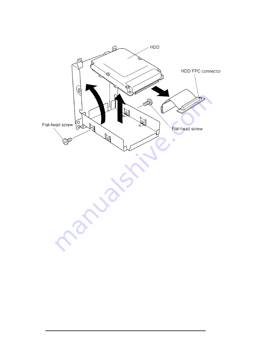
Carefully disconnect the FPC from the HDD pack. Use a thin object to pry each
side of the FPC connector a little at a time to avoid bending the pins, then grasp
the connector and pull it off (figure 4-10).
Figure 4-10 Removing the HDD
Installing the HDD
To install the T4900CT’s HDD, follow the steps below and refer to figures 4-7 through 4-10.
1.
Connect the FPC connector to the HDD and seat the HDD into the bottom half of
the case (figures 4-9 and 4-10).
2.
Align the screw holes in the HDD and case, then secure the HDD with
two flat-
head screws
at the end opposite the FPC connector (figure 4-9).
3.
Fit the plastic tab into slots on the bottom half of the case and seat the
HDD pack
cover
into the case (figure 4-7).
4.
Close the case and secure the remaining
two flat-head screws
.
5.
Apply a
new VOID seal
to the HDD pack.
6.
Seat the
HDD pack
in the computer and secure one
M2.5x4 screw
(figure 4-8).
7.
Fit the
tabs
on the HDD pack cover into
notches
on the computer and rotate the
cover into place. Secure the cover with
two M2.5x30 screws
(figure 4-7).
8.
Install the battery pack as described in section 4.2.
Summary of Contents for T-Series T4900CT
Page 20: ...T4900CT 2 3 Figure 2 1 Troubleshooting flowchart 1 2 ...
Page 176: ...B 2 T4900CT Figure B 2 Upper system board back ...
Page 178: ...B 4 T4900CT B 2 Lower System Board Figure B 3 Lower system board front ...
Page 179: ...T4900CT B 5 Figure B 4 Lower system board back ...
Page 199: ...T4900CT D 1 Appendix D USA Display Codes Table D 1 USA display codes ...


