2-10
T4900CT
Procedure 2
Connection Check
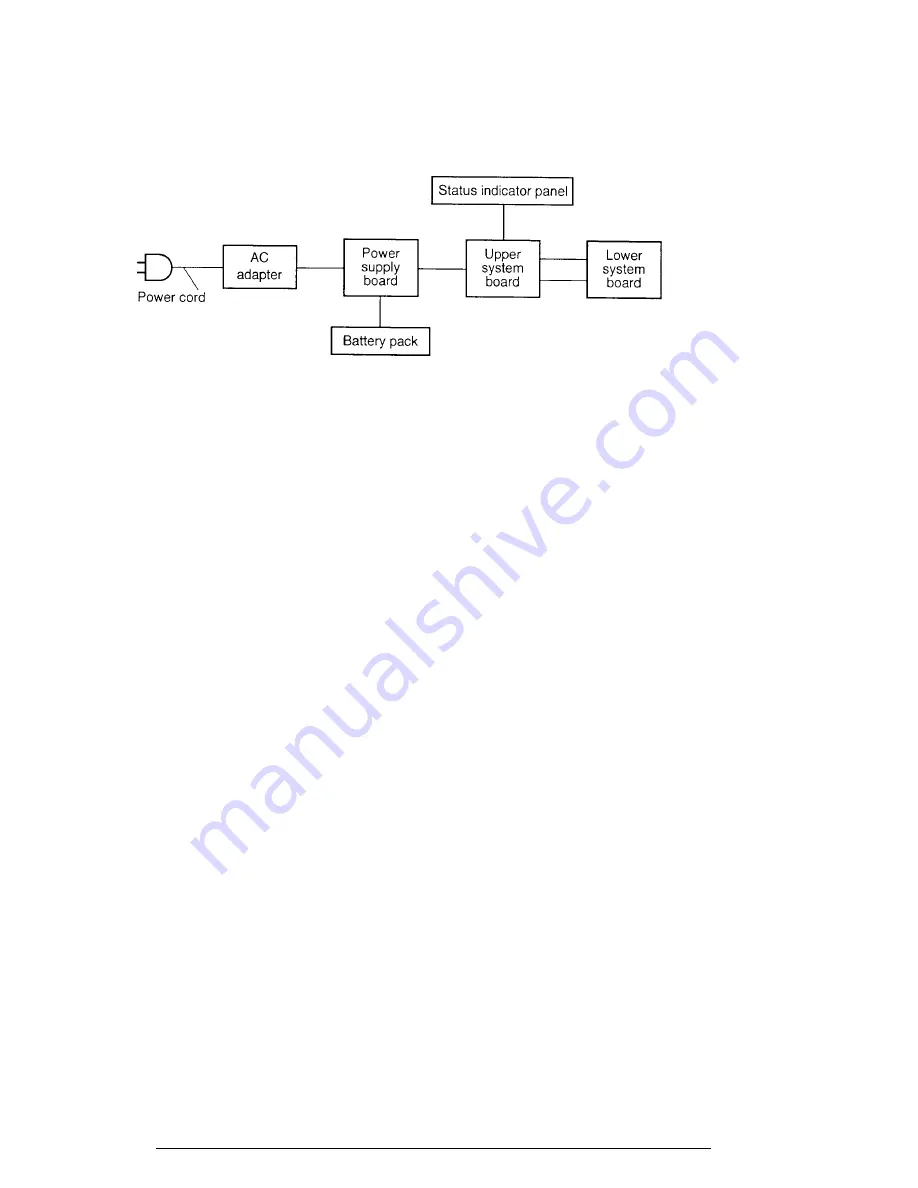
The power supply wiring diagram is shown below:
Any of the connectors may be disconnected. Perform Check 1.
If the battery power is not displayed, go to Check 1.
Check 1
Make sure the AC adapter’s cable and AC cord are firmly plugged into the DC IN
18 V socket and wall outlet. If these cables are connected correctly, go to Check
2.
Check 2
Connect a new AC adapter. If the battery capacity does not change on the status
indicator panel, go to Check 3.
Check 3
Make sure the battery pack is installed in the computer correctly. If the battery
pack is installed correctly, go to Procedure 3.
Summary of Contents for T-Series T4900CT
Page 20: ...T4900CT 2 3 Figure 2 1 Troubleshooting flowchart 1 2 ...
Page 176: ...B 2 T4900CT Figure B 2 Upper system board back ...
Page 178: ...B 4 T4900CT B 2 Lower System Board Figure B 3 Lower system board front ...
Page 179: ...T4900CT B 5 Figure B 4 Lower system board back ...
Page 199: ...T4900CT D 1 Appendix D USA Display Codes Table D 1 USA display codes ...


