4
Replacement Procedures
Figures
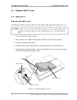
Figure 4-1 Removing Battery Cover..................................................................................... 4-8
Figure 4-2 Removing Battery Pack....................................................................................... 4-9
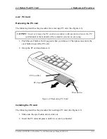
Figure 4-3 Removing PC Card ........................................................................................... 4-11
Figure 4-4 Removing Memory Slot Cover ......................................................................... 4-12
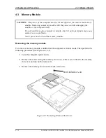
Figure 4-5 Removing Memory Module.............................................................................. 4-13
Figure 4-6 Removing HDD Slot Cover .............................................................................. 4-14
Figure 4-7 Removing HDD ASSY ..................................................................................... 4-15
Figure 4-8 Removing HDD ................................................................................................ 4-16
Figure 4-9 Removing MDC Modem................................................................................... 4-18
Figure 4-10 Removing Mini PCI Slot Cover...................................................................... 4-20
Figure 4-11 Removing Mini PCI Card ............................................................................... 4-21
Figure 4-12 Removing CPU Cover..................................................................................... 4-22
Figure 4-13 Removing Fan Module.................................................................................... 4-23
Figure 4-14 Removing CPU Holder ................................................................................... 4-24
Figure 4-15 Removing Cooling fin..................................................................................... 4-25
Figure 4-16 Removing CPU ............................................................................................... 4-25
Figure 4-17 Installing CPU................................................................................................. 4-26
Figure 4-18 Applying Silicon Grease ................................................................................. 4-27
Figure 4-19 Removing Keyboard Holder ........................................................................... 4-28
Figure 4-20 Removing Keyboard Hold Plate ..................................................................... 4-29
Figure 4-21 Keyboard Support Plate .................................................................................. 4-30
Figure 4-22 Removing CD-RO M Drive (1) ...................................................................... 4-32
Figure 4-23 Removing CD-ROM Drive (2) ........................................................................ 4-33
Figure 4-24 Removing Display Assembly (1) .................................................................... 4-35
Figure 4-25 Removing Display Assembly (2) .................................................................... 4-36
Figure 4-26 Removing Display Assembly (3) .................................................................... 4-37
Figure 4-27 Removing Touch Pad...................................................................................... 4-39
Figure 4-28 Removing BAT CON Holder.......................................................................... 4-41
Figure 4-29 Removing System Board................................................................................. 4-43
Satellite A10/TECRA A1/Satellite Pro A10 Maintenance Manual (960-445)
4-v
Summary of Contents for Satellite Pro A10 series
Page 11: ...Satellite A10 TECRA A1 Satellite Pro A10 Maintenance Manual 960 445 xi ...
Page 12: ...Chapter 1 Hardware Overview ...
Page 46: ...Chapter 2 Troubleshooting Procedures ...
Page 112: ...Chapter 3 Tests and Diagnostics ...
Page 199: ...Chapter 4 Replacement Procedures ...
Page 368: ...Appendices ...
Page 369: ...Appendices App ii Satellite A10 TECRA A1 Satellite Pro A10 Maintenance Manual 960 445 ...

