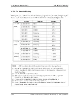
4.18 Fluorescent Lamp
4 Replacement Procedures
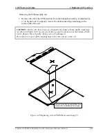
Removing the PCB-assembly cell
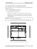
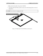
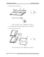
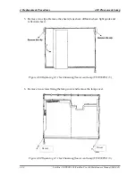
1. Remove the cell of the PCB assembly from the backlight assembly, as indicated by
(1) in Figure 4-49. Completely remove the double-sided tape remaining on the
reverse side of the cell.
CAUTION:
On the cell, three areas are bonded to the frame with the double-sided tape
(as shown in Figure 4-49, one area is at the top, and two areas are at the bottom of both
sides). Remove the cell gently, taking care not to damage it.
Be careful not to peel off the masking tape in the three areas on the cell.
セルをはずす.
両面テープ3箇所はがしながら
1
Remove the cell by peeling off the three
pieces of double-sided adhesive tape.
Figure 4-49 Replacing 14 Inch TMD fluorescent lamp (5)
Satellite A10/TECRA A1/Satellite Pro A10 Maintenance Manual (960-445)
4-69
Summary of Contents for Satellite Pro A10 series
Page 11: ...Satellite A10 TECRA A1 Satellite Pro A10 Maintenance Manual 960 445 xi ...
Page 12: ...Chapter 1 Hardware Overview ...
Page 46: ...Chapter 2 Troubleshooting Procedures ...
Page 112: ...Chapter 3 Tests and Diagnostics ...
Page 199: ...Chapter 4 Replacement Procedures ...
Page 368: ...Appendices ...
Page 369: ...Appendices App ii Satellite A10 TECRA A1 Satellite Pro A10 Maintenance Manual 960 445 ...

