66
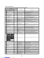
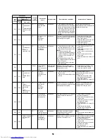
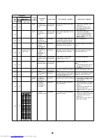
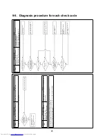
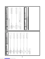
L30
L30
Detect indoor
addresses
Indoor
External
interlock for
indoor unit
Only the target
unit stopped
Signals are input into the external
error input terminal (CN80) for one
minute.
If an external device is connected
to the connector (CN80)
1) Check the external device error.
2) Check the indoor PC board error.
If no external device is connected
to the connector (CN80)
1) Check the indoor PC board error.
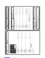
–
L31
–
I/F
Expanded I/C
error
Operation
continues
PC board (I/F) component error
Check the outdoor PC board (I/F).
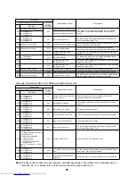
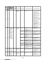
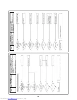
P01
–
–
Indoor
Indoor fan motor
error
Only the target
unit stopped
• Check the fan motor lock (AC
fan).
• Check wiring.
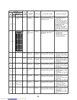
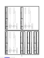
P03
P03
–
I/F
Discharge
temperature
TD1 error
All stopped
The discharge temperature (TD1)
exceeded 115 °C.
• Open and check the outdoor
service valve. (Gas, Liquid)
• Check the outdoor PMV clogging
(PMV1, 2, 4).
• Check the TD1 sensor resistant
characteristics.
• Check the refrigerant shortage.
• Check the four-way valve error.
• Check the SV4 circuit.
• Check the SV4 circuit.
(SV41 / SV42 / SV43 miswiring)
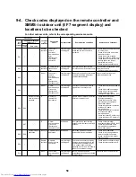
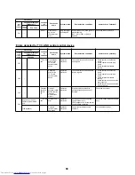
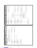
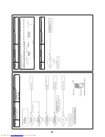
P04
P04
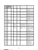
01:
Compressor 1
02:
Compressor 2
03:
Compressor 3
IPDU
High-pressure
SW error
All stopped
High-pressure SW was activated
• Check the connector connection
of the high-pressure SW.
• Check the Pd pressure sensor
error.
• Open and check the service
valve. (Gas, Liquid)
• Check the outdoor fan error.
• Check the outdoor fan motor
error.
• Check the outdoor PMV clogging
(PMV1, 2).
• Check the heat exchanger
clogging.
• Short circuit of the outdoor
suction / discharge air
• Check the SV2 circuit clogging.
• Check the outdoor PC board (I/F)
error.
• Check indoor fan error (caused
by low air volume).
• Check the opening status of
indoor PMV.
• Check the miswiring of the
communication line between
indoor and outdoor.
• Check the check valve error in the
discharge area.
• Check the gas balance SV4 valve
circuit.
• Check the SV5 valve circuit.
• Check the refrigerant
overcharging.
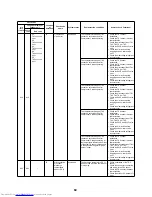
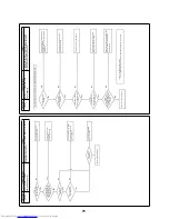
P05
P05
00: I/F
Open
phase
detected, Phase
sequence error
All stopped
• Open phase error was detected
when the power is turned on.
• Overvoltage / Undervoltage was
detected in the inverter DC
voltage.
Check the outdoor PC board (I/F)
error.
01:
Compressor 1
02:
Compressor 2
03:
Compressor 3
Inverter DC
voltage (Vdc)
error
(compressor)
P07
P07
01:
Compressor 1
02:
Compressor 2
03:
Compressor 3
IPDU
I/F
Heat sink
overheat error
All stopped
IGBT built-in temperature sensor
(TH) was overheated.
• Check power supply and voltage.
• Check the outdoor fan error.
• Check the heat sink cooling duct
clogging.
• Check the installation error
between IGBT and heat sink.
(Screw clamp, contact error)
• Check the A3-IPDU error.
(Outdoor IGBT built-in
temperature sensor (TH) error)
Check code
Location
of
detection
Check code
name
System status
Error detection conditions
Items to check (locations)
Local
remote
controller
7-segment display of
outdoor unit
Check
code
Sub code
Summary of Contents for MD-VNK802HEXE
Page 120: ...118 11Owner s Manual Excerpt ...
Page 137: ...135 12Installation Manual Excerpt ...


