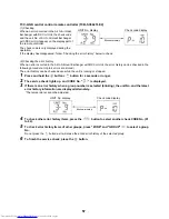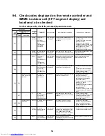
62
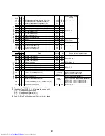
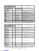
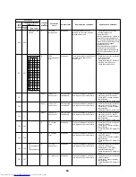
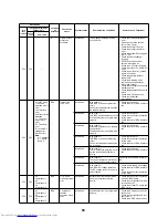
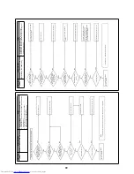
F24
F24
–
I/F
Pd sensor error
All stopped
The output voltage of the Pd sensor
is 0 (sensor open).
Pd > 4.15 Mpa while the
compressor is stopped
• Check the connector connection
of the Pd sensor.
• Check the Pd sensor error.
• Check the outdoor PC board (I/F)
error.
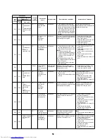
F29
–
–
Indoor
Indoor unit or
other error
Only the target
unit stopped
The indoor PC board does not work
properly.
Check the indoor PC board error
(EEPROM error).
F31
F31
–
I/F
Outdoor
EEPROM error
All stopped (*1)
The outdoor PC board (I/F) does not
work properly.
• Check power supply and voltage.
• Check the power supply noise.
• Check the outdoor PC board (I/F)
error.
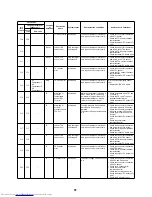
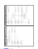
H01
H01
01:
Compressor 1
02:
Compressor 2
03:
Compressor 3
IPDU
Compressor
breakdown
All stopped
The inverter current detection circuit
detected overcurrent and stopped
operation.
• Check power supply and voltage
(AC200 V ± 10 %).
• Check the compressor error.
• Check the cause of overload
operation.
• Check the outdoor PC board (A3-
IPDU) error.
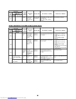
H02
H02
01:
Compressor 1
02:
Compressor 2
03:
Compressor 3
IPDU
Compressor
error (Lock)
All stopped
Overcurrent of the inverter
compressor was detected after
several seconds of activation.
• Check the compressor error.
• Check power supply and voltage
(AC200 V ± 10 %).
• Check the compressor line wiring
and open phase
• Check the connector and terminal
connection of the A3-IPDU board.
• Check case heater conduction.
(Activation error due to liquid
hibernation in the compressor)
• Check the outdoor PC board (A3-
IPDU) error.
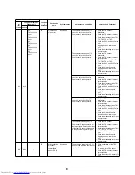
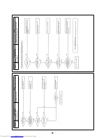
H03
H03
01:
Compressor 1
02:
Compressor 2
03:
Compressor 3
IPDU
Current
detection circuit
error
All stopped
Overcurrent was detected while the
inverter compressor is stopped.
• Check current detection circuit
wiring.
• Check the outdoor PC board (A3-
IPDU) error.
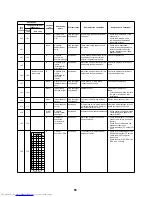
H05
H05
–
I/F
Misconnection
of outdoor
discharge
temperature
sensor (TD1)
All stopped
The discharge temperature (TD1)
does not rise while the compressor
1 is running.
• Check installation of the TD1
sensor.
• Check the connector connection
and wiring of the TD1 sensor.
• Check the TD1 sensor resistant
characteristics.
• Check the outdoor PC board (I/F)
error.
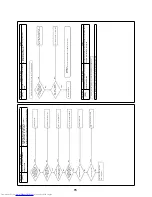
H06
H06
–
I/F
Low-pressure
protection
activation
All stopped
The low-pressure Ps is lower than
0.02 MPa.
• Open and check the service
valve.
(Gas, Liquid)
• Check the outdoor PMV clogging
(PMV1, 2).
• Check the SV2 and SV4 circuit
error.
• Check the low-pressure Ps
sensor error.
• Check the indoor filter clogging.
• Check the opening status of
indoor PMV.
• Check the refrigerant pipe
clogging.
• Check the outdoor fan operation
(HEAT).
• Check the refrigerant shortage.
*1 All stopped only for the center unit
The terminal unit continues running.
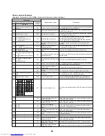
Check code
Location
of
detection
Check code
name
System status
Error detection conditions
Items to check (locations)
Local
remote
controller
7-segment display of
outdoor unit
Check
code
Sub code
Summary of Contents for MD-VNK802HEXE
Page 120: ...118 11Owner s Manual Excerpt ...
Page 137: ...135 12Installation Manual Excerpt ...

