14
4
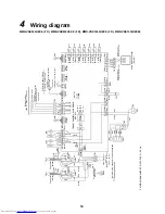
Wiring diagram
MMD-VNK502HEXE (-TR), MMD-VNK802HEXE (-TR), MMD-VNK1002HEXE (-TR), MMD-VNK1002HEXE2
*1
MMD-VNK
✽✽✽
HEXE-TR: 220–24
0 V~
, 5
0
Hz
C
o
nnect
or
(W
h
ite
)
Con
necto
r
(Black)
FM
1
F
M2
Ye
llo
w
Ye
llo
w
Y
e
llow
Ye
llo
w
C
C
Ye
llo
w
Y
el
low
Red
Red
Whit
e
W
h
ite
Blue
Blue
Ora
nge
Orange
Ora
nge
Orange
Blac
k
Blac
k
C
onne
ct
or
(R
e
d
*
6
)
Co
nnec
to
r
(W
hit
e *
6
)
43F
12
43F
11
43F
22
43
F2
1
Red
F02
T 15
A
25
0 V
~
Air
cond
itio
ner
indoo
r unit
Ear
th
P
o
wer su
pp
ly
for
in
do
or
u
n
it
22
0-
24
0
V
~
, 50 Hz
(*
1)
22
0 V
~
, 60
Hz
repre
s
e
nts t
he con
necto
r t
o
sw
it
ch be
twee
n
Extra
Hig
h a
nd
High.
Red
Wh
ite
TB1
Bl
a
c
k
P01
CN6
7
(Bla
c
k
)
F0
1
T 3
.1
5 A
25
0 V~
CN
7
0
1
(Whi
te)
C
N
702
(R
ed)
RY7
01
RY7
02
RY7
04
RY7
05
Red
Red
Oran
ge
Blue
Red
Oran
ge
Blue
Red
RY7
08
RY7
09
RY7
10
Indoor control circuit board
MCC1615
Po
wer
supply
DC 20 V
DC 15 V
DC 12 V
DC 7
V
SW7
01
CN760
(Whit
e)
DA
M
Blue
Yello
w
White
Red
Purpl
e
TB3
E
x
te
rnal out
put
(22
0 V~, un
der 1 A each)
O
p
er
at
io
n o
u
tp
u
t
Co
mm
on
Exte
rn
al d
a
m
p
e
r
ou
tpu
t
Abn
ormal /
Bypa
ss
mo
de
ou
tpu
t
C
N
704
CN705
CN70
6
C
N
6
1
(Y
ellow)
CN81
(B
lack)
CN82 (Blu
e)
Co
m
m
o
n
R
e
mo
te
co
nt
ro
lle
r op
e
rat
io
n
Fan spe
ed
Ope
ra
tion
*5)
E
x
te
rn
al input
(Opt
ion
)
N
o
vo
lt
ag
e a
-co
nta
ct i
n
put
Vo
lt
ag
e DC
(
1
2
V,
24
V)
i
n
p
u
t
PM
V
CN10
0
(B
ro
w
n
)
CN10
1
(Black)
CN10
2
(Red
)
CN10
3
(G
reen
)
CN10
4
(Y
ello
w)
CN10
5
(B
ro
w
n
)
CN10
6
(Wh
ite
)
TC1
TC2
TCJ
TFA
TS
A
TRA
TO
A
CN
041
(Blu
e)
C
N
04
0
(Blue
)
TB2
Blue
Blue
Black
Black
Wiri
ng
be
tw
ee
n
in
doo
r an
d o
u
td
oo
r
uni
t
Wiri
ng
fo
r t
h
e
re
mo
te c
o
nt
ro
lle
r
Wired
remot
e cont
ro
ller
(O
pti
on)
C
N
63
4
(R
ed
)
CN
34
(Red)
CN601
(Bl
ue)
C
N
60
2
(R
ed
)
Bla
ck
Wh
it
e
Black
FS1
Pi
nk
Pu
rp
le
Pi
nk
Pi
nk
TB4
TB5
MV
1
DMV
1
Gr
ay
Gr
ay
Bl
ac
k
Bl
ac
k
Re
d
Re
d
Summary of Contents for MD-VNK802HEXE
Page 120: ...118 11Owner s Manual Excerpt ...
Page 137: ...135 12Installation Manual Excerpt ...

