


CAN bus
The machine controllers communicate with each other on a Controller Area
Network (CAN) bus system. Using this network allows full integration of all the
different electrical components of the machine, allowing them to operate together
as one. The CAN bus system reduces the number of electrical components and
connections used on the machine and allows the number of wires in the wire
harness to be significantly reduced.
For model 31900, 31901, 31907 and 31909 machines, the TDM controller is the
only controller on the CAN bus presently. For model 31902 and 31903 machines,
the TDM controller and the Yanmar engine ECU are the only controllers on the
CAN bus presently. Additional controllers (for attachments) may be added
to the CAN bus in the future through the expansion port connector and/or the
telematics connector.
Each of the components that is controlled by the CAN bus link only needs four
(4) wires to operate and communicate to the system: CAN High, CAN Low,
power and ground. The key switch needs to be in the RUN or START position
for the components on the network to be activated.
Two specially designed, twisted wires form the CAN bus. These wires provide the
data pathways between the components on the network. The engineering term
for these cables are CAN High and CAN Low. The CAN bus wires are red/white
(CAN-High) and black/white (CAN Low). At each end of the CAN bus is a 120
ohm termination resistor; refer to
CAN bus Terminator Resistors (page 6–56)
.
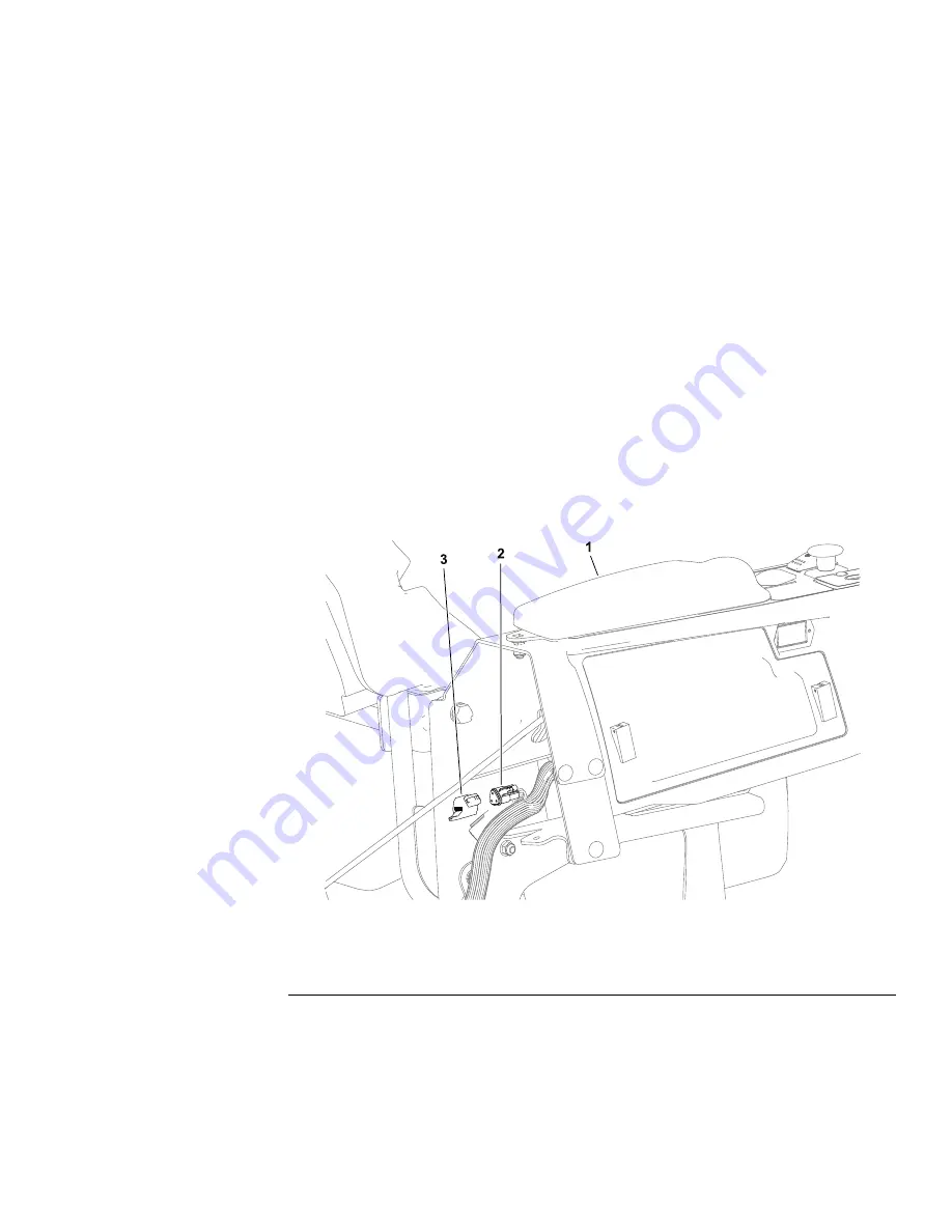
Testing the CAN bus
g305596
Figure 84
1.
Operator’s console
3.
Cover
2.
DIAG connector
1. Park the machine on a level surface, lower the cutting unit (or attachment),
engage the parking brake, set the key switch to the O
FF
position and remove
the key from the key switch.
2. The Toro DIAG connector is part of the CAN bus and is located at the rear
of the operator’s console. Remove the connector cover from the machine
wire harness and use a multimeter (ohms setting) to check the Toro DIAG
connector.
Groundsmaster
®
3200, 3300 and 3310
Page 6–17
Electrical System: Testing the Electrical Components
19240SL Rev A
Summary of Contents for Groundmaster 31900
Page 4: ...Reader Comments Page 4 Groundsmaster 3200 3300 and 3310 19240SL Rev A...
Page 16: ...Safety Safety and Instructional Decals Page 1 8 Groundsmaster 3200 3300 and 3310 19240SL Rev A...
Page 86: ...Engine Service and Repairs Page 4 24 Groundsmaster 3200 3300 and 3310 19240SL Rev A...
Page 332: ...Operator Cab Service and Repairs Page 9 18 Groundsmaster 3200 3300 and 3310 19240SL Rev A...
Page 355: ......