TOHATSU TLDI MD 115A SERIES Service Manual Download Page 137

5

5-15

TLDI  115A  2007

3. Inspection Items

1) Removing Power Unit
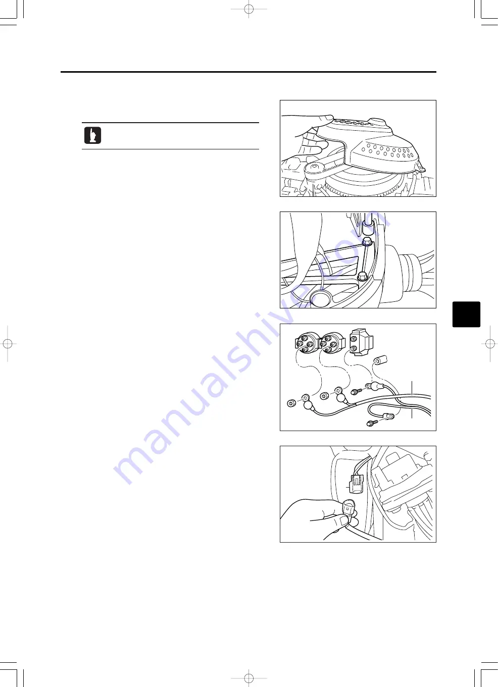
1.

Remove ring gear cover.

2

1

3.

Remove bracket cover, and then, remove battery cables

1

and PTT cable 

2

from solenoid switch and other parts.

3

4.

Disconnect connector 

3

of PTT switch.

2.

Remove clamps that secure shift cable and remote control

cable from bottom cowl.

Disconnect battery cables from battery terminal.

MD115A̲ch05̲E̲2校̲070606.qxd  07.6.6 6:30  PM  ページ 15

Summary of Contents for TLDI MD 115A SERIES

Page 1: ...OB No 003 21060 0 07 05 NB 2600 OB No 003 21060 0 07 05 NB 2600 Printed in Japan MD115A cover E qxd 07 6 8 2 32 PM 1...

Page 2: ...al is utilized so that our customers can always use their outboard motor with full satisfaction Information for securing of safety Safety Statements The following safety statements are found throughou...

Page 3: ...ft 1 3 kgf m GR EA SE OBM OBM OBM OBM 6 N m 4 lb ft 0 6 kgf m G17 G17 G17 BO ND G17 SOC OI L C OM P GM GM SOC SOC SOC Electric Parts Starter Motor 1 Starter Motor 1 1 1 Positive Brush 2 1 2 Negative...

Page 4: ...dized mostly with metric system in the world the metric system includes different kinds of unit systems Though the metric system was established expecting that a single unit system is used in the worl...

Page 5: ...G17 G17 BO N D Konishi Bond G17 2st O I L TB 1342 1342 LT 518 518 Oil Compound Shinetsu Silicon S O C O IL CO M P SOC SOC Molybdenum Grease Moly Paste 500 G REASE MOL MOL Inspections and Adjustments S...

Page 6: ...3 9 1 Inspection of Cooling Water Passage 3 9 2 Flushing with Water 3 10 3 Inspection of Compression Pressure 3 13 6 Power Unit 3 14 1 Inspection of Drive Belt 3 14 2 Adjustment of Drive Belt Tension...

Page 7: ...ng Coil Bracket Parts 5 50 26 Assembling Crank Case Head Parts 5 50 27 Installing Air Chamber 5 51 28 Attaching Coil Bracket 5 53 29 Attaching Recirculation Hoses 5 54 30 Installing Alternator 5 55 31...

Page 8: ...Rectifier Complete 8 9 12 Inspection of Throttle Position Sensor 8 10 13 Inspection of Water Temperature Sensor 8 10 14 Inspection of Power Relay 8 11 15 Inspection of Air Injectors 8 11 16 Inspection...

Page 9: ...1 Battery Capacity 10 14 2 Connection of Battery Cables 10 14 3 Installation of Battery ies 10 14 7 Accessories and Meters 10 15 1 Accessories 10 15 2 Installation of Meters 10 15 3 Wiring Remote Cont...

Page 10: ...11 Service Information Service Data Inspections and Adjustments Fuel System TLDI Power Unit Lower Unit Cowl Bracket and PTT Electrical System Troubleshooting Rigging Wiring Diagram INDEX OK r min MD11...

Page 11: ...g instruments 1 5 3 List of Special Tool 1 6 4 Pre delivery Inspection 1 10 1 Steering Handle 1 10 2 Gear Shift and Throttle 1 10 3 Engine Oil 1 10 4 Gear Oil 1 10 5 Check quantity of engine oil 1 11...

Page 12: ...g indoors 3 Protection Wear a pair of goggles working gloves and safety shoes to protect skin from chemicals and oils and eyes from particles generated by grinding or polishing Avoid contact of oil gr...

Page 13: ...cribed in this manual and use tightening torque specified 6 Recommendations on service Remove foreign substances and dirt from outboard motor and individual parts by cleaning Apply recommended oil or...

Page 14: ...s and other detailed parts For the components that use many bolts and nuts such as cylinder head or crank case tighten the fasteners in the order shown by the numbers to prevent uneven tightening If t...

Page 15: ...25 mm 25 to 50 mm 50 to 75 mm Cylinder gauge 4 to 6 mm 10 to 25 mm 25 to 30 mm 50 to 75 mm Ring gauge 23 88 Dial gauge minimum graduation of 0 01 Thickness gauge 0 03 to 0 3 mm V block Surface plate...

Page 16: ...ng Propeller Shaft Housing Puller Ass y P N 353 72252 0 Removing spring pin Spring Pin Tool A P N 369 72217 0 Installing spring pin Spring Pin Tool B P N 369 72218 0 Bevel Gear Bearing Puller Ass y P...

Page 17: ...ring Measuring backlash Backlash Measuring Tool Clamp P N 3B7 72720 0 Used to attach dial gauge when measuring backlash Dial Gauge Plate P N 3B7 72729 0 Measuring backlash between forward A gear and p...

Page 18: ...eal Oil Seal Attachment P N 3T1 99820 0 79 5 x 39 5 Bearing install Tool P N 3T1 99900 0 Attaching drive shaft bearing Attaching air compressor bearing Bearing Attachment P N 3T1 99905 0 51 5 x 39 5 O...

Page 19: ...1 9 1 TLDI 115A 2007 Used in combination with driver rod Attaching propeller shaft housing oil seal Oil Seal Attachment P N 3Y9 99820 0 49 5 x 29 5 MD115A ch01 E 2 070529 qxd 07 6 6 5 36 PM 9...

Page 20: ...check that the throttle operations are smooth 4 Engine Oil Supply engine oil Engine Oil Genuine MD Platinum Oil Oil for two stroke direct injection engine recommended by the outboard manufacturer OIL...

Page 21: ...8gal 1 4L 0 37gal Warning Oil Level Sensor Warning lamp left lamp blinks Buzzer sounds intermittently Three short beeps every two minutes CAUTION When quantity of faills below 1 4L 0 37gal oil warning...

Page 22: ...mixed with engine oil will cause engine trouble 8 Inspection of PTT Unit 1 Operate PTT switch to check that outboard motor tilts up down smoothly 2 Operate PTT switch to check that tilting up down out...

Page 23: ...eck that engine stops Switch Panel Model Remote Control Model OFF ON START RUN OFF ON OFF START OFF START2 3 ON OFF START2 3 OFF ON START RUN OFF 5 OFF ON START RUN OFF 4 3 Press stop switch 4 hard or...

Page 24: ...75 x 21 0 3 x 324 x 533 15P 75X15 P K L H 13 1 2 10 Propeller Selection Select a propeller that is best suited to type of boat and application CAUTION Wrong selection of propeller can cause adverse ef...

Page 25: ...rd motor on the boat use trim tab to achieve balance between port and starboard steering loads Loosen trim tab nut 2 adjust angle of trim tab 1 as described below and then tighten the nut to specified...

Page 26: ...er leaks at the engine 4 After test run use flushing kit and fresh water to wash cooling water path by idling engine Trolling Engine Speeds 700 800 900 50 r min RPM 4 Run at 3 000 r min or half of WOT...

Page 27: ...p Dimensions 2 3 2 Cooling Water System Diagram 2 4 3 Specifications 2 6 4 Warning Indication List Display for abnormalities during operation 2 8 5 Torque Specifications 2 10 6 Maintenance Data 2 12 7...

Page 28: ...04 Transom L mm in 517 20 35 Transom UL mm in 644 25 35 E mm in 854 33 62 H mm in 618 24 33 I mm in 634 24 96 J mm in 31 70 1 22 2 76 K mm in 598 23 54 Transom L mm in 967 38 07 Transom UL mm in 1084...

Page 29: ...125 5 mm 4 94 in 125 5 mm 4 94 in 121 mm 4 76 in 121 mm 4 76 in 13 5 mm 0 53 in 17 5 mm 0 69 in 51 mm 2 01 in 254 mm 9 98 in 353 mm 13 90 in 187 mm 7 36 in M12P1 25 163 5 mm 6 44 in 163 5 mm 6 44 in 1...

Page 30: ...2 4 Service Data TLDI 115A 2007 2 Cooling Water System Diagram 1 2 3 4 5 6 7 q 8 9 0 w e r MD115A ch02 E 2 070529 qxd 07 6 6 5 40 PM 4...

Page 31: ...rive Shaft Housing Cylinder Lower Section Water Discharging Passage in Drive Shaft Housing Discharging Exhaust System Cover Cylinder Head Head Cover Thermostat Cylinder Lower Section Water Feed Passag...

Page 32: ...ing Impeller type Reed Valve Loop 5 Port Thru Hub Exhaust Electro magnetic Induction Inductive Ignition 1 3 2 4 IZFR5J NGK 12V 490W 12V 100 120AH 800 1 000 C C A Exhaust System Air Intake System Cooli...

Page 33: ...ket Steps Adjustable 2 Degrees 4 12 2 Degrees Adjustable 3 Degrees 67 4 Degrees 33 33 mm in 31 70 1 22 2 75 Grade 2 Angle with reference to horizontal propeller shaft when transom angle is 12 degrees...

Page 34: ...hing Flashing Flashing Low speed ESG Flashing Flashing Flashing Forced idling Flashing Flashing Flashing Low speed ESG Flashing Flashing Flashing Flashing Flashing Flashing Flashing Flashing Flashing...

Page 35: ...TPS malfunction 2 TPS1 and TPS2 TPS malfunction 1 TPS1 or TPS2 TPS power supply malfunction 2 TPS1 and TPS2 TPS power supply malfunction 1 TPS1 or TPS2 Air injector malfunction Fuel injector malfunct...

Page 36: ...1 1 5 Spark Plug 16 M12 x 1 25 25 18 2 5 MAP Sensor 10 M6 x 1 0 Screw 2 1 4 0 2 Rectifier 10 M6 x 1 0 Bolt 9 7 0 9 Engine Mount Bolt Engine Base Drive Shaft Housing 14 M10 x 1 25 Bolt 20 14 2 0 40 29...

Page 37: ...ump Bolt 9 7 0 9 Trim Rod Guide 80 58 8 0 Tilt Rod Guide 130 94 13 0 M4 7 M4 x 0 7 1 5 1 1 0 15 M5 8 M5 x 0 8 4 3 0 4 M6 10 M6 x 1 0 6 4 0 6 M8 13 M8 x 1 25 13 9 1 3 M10 17 M10 x 1 25 27 20 2 7 Tighte...

Page 38: ...learance The gap between cylinder and piston Measure clearance between piston ring and ring groove 23 00 mm 0 9060 in Top 0 04 0 08 mm 0 0016 0 0032 in Second 0 04 0 08 mm 0 0016 0 0032 in Third 0 04...

Page 39: ...f over specified limit 0 80 mm 0 0315 in 0 80 mm 0 0315 in 0 80 mm 0 0315 in 0 040 mm 0 0016 in Repair or replace depending on the extent of damage Repair using 400 to 600 grit sandpaper 0 05 mm 0 002...

Page 40: ...i 0 71kg 10 Vapor Separator Second 0 10 0 25 mm 0 004 0 010 in 0 2 mm 0 008 in or less Tension 100 230N Tension measuring instrument by Yunitta Piston diameter maximum diameter Measure at a point 10mm...

Page 41: ...s no longer conform to standard values Replace with new part 12 mm 0 47 in 0 2 mm 0 008 in 32 mm 1 26 in When the fuse burns out After repairing the cause of the burn out replace with a new fuse When...

Page 42: ...67 psi 40 75kg Standard Values Pump Assembly 682 23 1 fl oz 150 mesh 96 9 mm 3 815 in Upper chest 0 24 MPa 34 1 psi 2 4 kg Lower chest 0 12 MPa 17 1 psi 1 2 kg Spool check valve opening pressure Relie...

Page 43: ...new assembly Replace with new part Replace if over specified limit Replace with new part When lip area shows deterioration heat discoloration or damage or when reduces interference to 0 5 mm 0 02 in o...

Page 44: ...o O Ring High Tension Cord a b a Plug cap side b Ignition coil side Spark Plug Cap Interior Advancer Arm Sliding section Throttle Cam Sliding section Shift Arm Sliding section Ball Joint Cap Sliding s...

Page 45: ...k Shaft B G Apply to rolling sections Collar O Ring Apply to rolling sections Adapter Hose Joint Apply to embededed sections M10P1 0 sections Adapter Hose Joint Apply to embededed sections M10P1 0 sec...

Page 46: ...e Gasket Shift Lever Shaft Holder Mounting Bolt Screw section Shift Lever Shaft Holder Sliding section and interior small amount Cam Rod Bushing Whole circumference Cam Rod Bushing O Ring 1 9 6 8 Cam...

Page 47: ...elow neck Tilt Rod Nut PTT Sensor Bolt Screw section PTT Switch Terminal section PTT Oil Oil equivalent to ATF DEXRON III Bolt Shift Lever Screw section Shift Lever Sliding section Shift Rod Grommet R...

Page 48: ...er 3 10 3 Inspection of Compression Pressure 3 13 6 Power Unit 3 14 1 Inspection of Drive Belt 3 14 2 Adjustment of Drive Belt Tension 3 15 3 Inspection of Spark Plugs 3 16 4 Inspection of Thermostat...

Page 49: ...ring Pin Tool A P N 369 72217 0 Installing spring pin Spring Pin Tool B P N 369 72218 0 Compression Gauge P N 3AC 99030 0 Measuring compression pressure Measuring air rail fuel pressure and air pressu...

Page 50: ...ery cables Battery Installation electrolyte level specific gravity Oil Tank Oil Pipe Oil Filter Propeller Blade Bent damage wear Gear Oil Replace Replace Replace Replace Replace oil or replenish Check...

Page 51: ...cessary Remove cover stay 1 Add or remove washer s 2 for adjustment CAUTION Remove washer s if too much play Add washer s if too much tightening is needed 1 2 2 Oil Filter and Oil Tank Only clean if d...

Page 52: ...d oil When air is bled from the oil set the key switch to OFF The oil pump stops automatically at approximately one minute 4 Pull twice Beep Beep Beep Beeps three times 6 Pull stop switch 4 twice with...

Page 53: ...nts TLDI 115A 2007 4 Fuel System 1 Inspection of Fuel Pipes and Joints Check the fuel system piping for fuel leak dirt deterioration and damage and replace or clean parts if necessary MD115A ch03 E 2...

Page 54: ...Compressor Air Filter 1 Replace the air filter if it is severely clogged The paper strainer of air filter turns brownish when it is clogged Replace the part if it is brownish Be sure to attach the fi...

Page 55: ...ssure inspection valve 1 CAUTION When attaching pressure gauge ass y cover the joint of inspection valve and gauge with rag to prevent spread of fuel that leaks Screw in the pressure gauge carefully u...

Page 56: ...move gauge CAUTION Be careful not to let the fuel in the gauge leak when removing the gauge 7 Attach the cap 5 Cooling System 1 Inspection of Cooling Water Passage 1 Check that cooling water intake is...

Page 57: ...water outlet to 3 and run water Set shift lever to neutral N and start engine Check that cooling water check port discharges water and run engine for 3 to 5 minutes at idle speed Stop engine and stop...

Page 58: ...o 5 minutes 1 2 3 4 1 2 5 CAUTION The flushing can be made without running the engine Water pressure 0 12 0 2MPa 1 74 29 0psi 1 2 2 0kgf cm2 4 Remove flushing attachment 5 Check if seal rubber 3 and O...

Page 59: ...Speed meter pipe is put on the nipple of gear case ass y After gear case has come down slightly remove pipe from nipple 3 Check following parts 7 Bolts M8 4 pcs 8 Washers 4 pcs 9 Pump Case Upper 0 Pu...

Page 60: ...lug caps and then all spark plugs 5 Install compression gauge to plug hole Compression pressure is affected much by cranking speed and normally changes in the range from 10 to 20 Charge the battery 7...

Page 61: ...2 Check drive belt for wear and damage on the inner and outer faces while turning flywheel clockwise Check if oil or dirt is adhered to the belt Replace with new one if any of the problems exists Crac...

Page 62: ...the securing bolts to fix the compressor Deflection of Belt 4 6 mm 0 16 0 24 in when pushing the belt with 20 N 2 0 kg CAUTION Be careful that oil or grease does not adhere to the belt CAUTION Perfor...

Page 63: ...of Spark Plugs 1 Remove plug caps and then spark plugs Spark Plug Gap a Standard Value 0 7 0 8 mm 0 029 0 032 in Spark Plug 25 N m 18 lb ft 2 5 kgf m a 2 1 2 2 Clean spark plug electrodes 1 by using...

Page 64: ...er Temperature Valve Lift a 75 C 167 F 4 5 mm 0 177 in or more 3 Hang thermostat 3 in the water contained in vessel 4 Put thermometer in the water and warm up water to measure valve opening temperatur...

Page 65: ...UTION Adjust cable joint screw in length a to 10mm 0 39in or over a 7 Attach cable joint washer and R shaped pin to advancer arm 8 Check if throttle control can be made smoothly If necessary readjust...

Page 66: ...osition N 6 Adjust cable joint screw in length so that the pin of shift lever is aligned with the hole of cable joint 1 4 3 2 5 CAUTION Adjust cable and cable joint screw in length a to 10mm 0 39m or...

Page 67: ...of normal revolution 2 Inspection of PTT Fluid Quantity 1 Fully tilt up outboard motor and lock with tilt stopper 1 2 WARNING Be sure to lock outboard motor with tilt stopper after tilting up Danger...

Page 68: ...n of Gear Oil Quantity 1 Tilt down outboard motor to make it vertical 2 Remove upper oil plug 1 and gasket 2 and check level of gear oil in the gear case Gear Oil Hypoid Gear Oil API GL 5 SAE 90 OIL L...

Page 69: ...2 and then new gasket 3 and lower oil plug 1 quickly Gear Oil Hypoid Gear Oil API GL 5 SAE 90 Gear Oil Quantity 900 cm3 30 4 fl oz OIL 2 1 a 2 1 2 1 3 a 3 3 Check gear oil for presence of metal partic...

Page 70: ...ntained Pressure 0 05 MPa 7 psi 0 5 kgf cm2 3 Inspection of Gear Case for leakage 1 Drain gear oil 2 Remove upper oil plug 1 and connect a commercially available leakage tester to this hole Rotating p...

Page 71: ...d to the components Clean if necessary 1 1 2 CAUTION Anode protects outboard motor from galvanic corrosion Do not paint or apply grease or oil to anode Doing so disables the anode 2 Check anode 1 a an...

Page 72: ...er if adhered to skin If gets in eye flush well with fresh water for 15 minutes and have ophthalmologic evaluation immediately First Aid in Emergency if swallowed Gargle using much water drink much wa...

Page 73: ...ppears from a 1 a a G REASE OBM OBM OBM G REASE OBM OBM OBM a 1 G REASE OBM OBM OBM G REASE OBM OBM OBM LIT G REASE LIT 2 Apply grease to propeller shaft spline 3 Only under pinion on splines outside...

Page 74: ...4 28 7 Assembly of Vapor Separator Ass y 4 29 8 Removing FFP Ass y 4 29 9 Disassembly and Inspection of FFP 4 29 10 Assembly of FFP Ass y 4 30 11 Attaching FFP Ass y to Cylinder 4 32 12 Inspection of...

Page 75: ...chment P N 3T1 99905 0 51 5 x 39 5 Used to press fit crank case head oil seal Oil Seal Attachment P N 3T1 99820 0 Piston Slider P N 3T1 72871 0 Assembling piston for air compressor Caulking clamps mad...

Page 76: ...Hose 1 I D 7 Liter 1 200 Fuel hose nipple Fuel filter 13 Clip 12 5 14 Fuel Filter 1 14 1 Cup 1 2st O I L 2st OIL P L Fig 6 14 2 Filter 1 14 3 O Ring B 1 14 4 O Ring A 1 14 5 Float 1 15 Nut 1 M8 16 Wa...

Page 77: ...1 3 1 10 1 12 1 1 1 2 1 5 1 9 1 11 1 11 1 8 1 4 1 13 Yellow Blue 1 15 4 5 3 2 1 19 1 14 1 16 3 6 1 2st OIL 2st O I L 2st OIL 2st O I L 2st OIL 2st O I L 15 N m 11 lb ft 1 5 kgf m 3 2 N m 2 3 lb ft 0 3...

Page 78: ...sitive 1 1 10 Cable Terminal Negative 1 1 11 Cable Terminal Grommet 2 1 12 Cable Terminal Grommet Upper 1 1 13 FFP Cord 1 1 14 FFP Cord Cover 1 1 15 Bolt 1 M5 L 12mm W SW 1 16 Washer 1 M5 1 17 Pipe Gr...

Page 79: ...27 7 4 28 5 6 4 5 19 23 16 12 14 15 N m 11 lb ft 1 5 kgf m 2st OIL 2st O I L 2st OIL 2st O I L 15 N m 11 lb ft 1 5 kgf m TB 1342 1342 S O C O IL CO M P GM SOC SOC S O C O IL CO M P GM SOC SOC 2st OIL...

Page 80: ...2 O Ring 2 5 5 1 20 Air Regulator 1 20 1 O Ring 2 5 20 1 20 2 O Ring 2 5 5 1 21 Fuel Injector Holding Plate 1 22 Fuel Injector Holding Plate 3 23 Air Hose Ass y 1 23 1 O Ring 1 9 9 8 2 24 Fuel Hose A...

Page 81: ...kgf m 2st OIL 2st O I L 2st OIL 2st O I L 2st OIL 2st O I L 2st OIL 2st O I L 2st OIL 2st O I L 9 N m 7 lb ft 0 9 kgf m 15 N m 11 lb ft 1 5 kgf m TB 1342 260 N m 190 lb ft 26 kgf m 1342 LIT G REASE LI...

Page 82: ...Cylinder 1 1 13 Compressor Housing 1 1 14 Compressor Housing Gasket 1 1 15 Oil Seal 25 45 8 1 1 16 Bolt 4 M6 L 25m W PW 1 17 Dowel Pin 4 10 2 1 18 Driven Pulley 1 1 19 Driven Pulley Nut 10 P1 25 1 1...

Page 83: ...4 10 32 37 4 37 3 37 2 37 1 37 23 19 22 21 22 20 24 11 18 1 Cylinder 4 Air Chamber 13 3 Air Chamber 12 2 Air Chamber 11 1 Air Chamber 2 Cylinder 3 Cylinder 4 Cylinder Air Compressor A B C D 10 N m 7 l...

Page 84: ...Oil Pipe 1 Oil pump 3 Cylinder 18 Oil Pipe 1 Oil pump 4 Cylinder 19 Oil Pipe 1 Oil pump Nipple joint 20 Oil Pipe 1 Nipple joint Air compressor 21 Nipple Joint 1 22 Lead Wire Band 104 4 23 Clip 7 8 1...

Page 85: ...sumption and lower emission as well as powerful performance that is one of outstanding features of two stroke engines 2 Air assisted low pressure direct fuel injection The air assisted low pressure di...

Page 86: ...nction together to detect openings of intake valve throttle butterfly and throttle advancer arm of the throttle body and transmits the signals to ECU 2 CPS Crank Position Sensor CPS detects the crank...

Page 87: ...through the set piece The component is controlled by ECU to supply the amount of fuel that is best suited to the current engine operation conditions based on the information from sensors 7 MAP Manifol...

Page 88: ...us fuel distribution in the combustion chamber in the high speed range TPS Throttle Position Sensor Input Sensor Switch Control ECU Output Actuator ECU Engine Control Unit CPS Crank Position Sensor WT...

Page 89: ...differential pressure is kept to 0 070MPa 10psi for proper combustion The gasoline that is not used here is decompressed and returned to 4 through FFP case 9 The returned gasoline contains small amoun...

Page 90: ...split into the ports of the following nine components here cylinder 1 crank case 4 cylinder 2 crank case 5 cylinder 3 crank case 6 cylinder 4 crank case 7 air compressor 8 air box 1 9 air box 2 0 air...

Page 91: ...The oil that is deposited in the air box flows to interior of crank case y of cylinder 2 to lubricate it Then the oil that is deposited in the scavenging passage of each cylinder flows from 1 cylinder...

Page 92: ...oth to prevent fuel from spurting when decompressing WARNING Be sure to decompress fuel and air before disassembling fuel system components Disassembling fuel system components can cause spurting of c...

Page 93: ...ring and insert bladed screw drivers from both sides to remove it up straight evenly CAUTION Handle fuel injectors carefully Impacting their tips can cause malfunction Be careful not to drop O ring lo...

Page 94: ...3 0 2 Attach O rings 5 and 6 to air injector 4 3 Attach O rings 9 and 0 to air regulator 7 and fuel regulator 8 1 3 2 2st OIL 2st O I L 78 9 0 5 4 6 CAUTION To avoid incorrect installation of the fuel...

Page 95: ...ttach the insert q in a correct orientation shown by arrow A Correct Wrong Face passage opening toward you View from Arrow A 5 Attach fuel injector adapter e and fuel injector 1 to the air rail 6 Atta...

Page 96: ...lator by using hose clamp 2 Do not reuse hose clamp Always use new one Clamp Pliers P N 3T5 72864 0 2 Removing hose clamp Cut joint of hose clamp 2 and remove the clamp 2 CAUTION Remove hose clamp wit...

Page 97: ...h air hose ass y 1 to air compressor hose joint adapter with fasteners tightened to specified torque from air compressor air 1 to air compressor cooling water 2 to FFP fuel 3 to cylinder air 4 from ex...

Page 98: ...s 5 and 6 when they are removed 2 Remove high pressure fuel filter 3 from mounting bolt 4 and exhaust cover 3 4 7 2 Attaching Fuel Hose Ass y Reverse the removing steps Fuel Filter Band Securing Bolt...

Page 99: ...g steps to drain fuel from vapor separator 1 Loosen air vent screw 1 and then drain screw 2 4 2 7 6 5 1 3 Use rag to catch fuel that spills from the part 2 when it is loosened 2 Pull out following hos...

Page 100: ...hen remove float valve 1 and float 2 1 2 2 Inspection of Vapor Separator 1 Check needle valve 1 for deformation and wear 2 Check float 2 for deformation crack and other defects Replace if necessary 3...

Page 101: ...ft 0 16 kgf m 5 Drain Screws Tighten two screws 6 O Rings 2 pcs Draw Screw 5 1 6 N m 1 1 lb ft 0 16 kgf m O Ring 6 Genuine Engine Oil 2st O I L 7 O Ring 8 Tighten Screw 9 Tighten Screw Screws 8 and 9...

Page 102: ...FFP Vapor Return Hose 4 FFP Vapor Separator Fuel Hose 5 Vapor Separator FFP 3 Loosen two bolts 6 and remove FFP Use rag to catch fuel that spills from each hose when it is disconnected 9 Disassembly...

Page 103: ...adhesive 8 ThreeBond 1342 TB 1342 1342 Replace metal washer 9 with new one if FFP is disassembled 2 Attach pipe grommet 1 and lower grommet w to FFP q Pipe Grommet 1 Lower Grommet w Genuine Engine Oi...

Page 104: ...rresponding flat terminals and Push down cables terminals to connect terminals securely Be careful that the cords are not caught Attach cord cover y and clamp u to the body by using spacer washer t an...

Page 105: ...ut fuel hose 3 fuel return hose 4 and vapor return hose 5 and secure them by using hose clips 2 Attach high pressure fuel hose 6 to FFP 1 Use clamp of FFP ass y to secure FFP cord connector High Press...

Page 106: ...6 Apply specified pressure to check that no air leaks through check valve located in the fuel pump Replace fuel pump if necessary Specified Pressure 0 05 MPa 7 psi 0 5 kgf cm2 Specified Vacuum Pressur...

Page 107: ...Fuel System TLDI 4 34 TLDI 115A 2007 Air Piping of Air Compressor Intake Exhaust Air Compressor Air Filter Air Rail MD115A ch04 E 2 070605 qxd 07 6 6 5 42 PM 34...

Page 108: ...4 4 35 TLDI 115A 2007 Structure of Air Compressor 7 8 9 0 q 6 5 a y t 4 r e u i o s p f d j h j g k l 1 3 2 MD115A ch04 E 2 070605 qxd 07 6 6 5 42 PM 35...

Page 109: ...ng pulley of the air compressor 2 Removing Air Compressor Remove compressor by using the following steps 1 Loose the clamps of oil pipe 1 Recirculation pipe 2 and cooling water pipe 3 at compressor si...

Page 110: ...amage and wear on both faces 2 Check drive belt for missing tooth teeth and adherence of oil Replace the belt with new one if any of the above problems exists Crack or chip of the belt if any can be f...

Page 111: ...sor cylinder 2 Fix crank shaft at its lower end by using a vice loosen driven pulley securing nut and then remove driven pulley CAUTION Be careful not to damage the crank pin 1 area when fixing crank...

Page 112: ...r before removing bearing 2 Heating of compressor housing can also be made by using a heat gun or heat lamp 7 Inspection of Cylinder and Piston 1 Clean compressor cylinder compressor head and compress...

Page 113: ...Bearing Attachment 2 P N 3T1 99905 0 Driver Rod 1 P N 3AC 99702 0 Oil Seal Attachment 4 P N 3T1 99820 0 2st OIL 2st O I L 3 1 2 2 Apply two stroke engine oil to periphery of oil seal 5 lithium grease...

Page 114: ...wer end by using a vice 2 Attach collar 3 O ring 4 and driven pulley 5 and tighten nut 6 to the specified torque Driven Pulley Nut 6 50N m 36 lb ft 5 0kgf m 6 5 4 3 2 2st OIL 2st O I L 1 7 CAUTION Be...

Page 115: ...r CAUTION Be careful not to scratch piston when attaching the rings Piston Slider 4 P N 3T1 72871 0 1 4 3 2st OIL 2st O I L 2 Apply two stroke engine oil to cylinder inner wall 3 piston periphery and...

Page 116: ...f m Cylinder Head Bolt 8 9N m 7 lb ft 0 9kgf m 3 Install head 5 reed valve ass y 6 and gasket 7 by using bolt 8 Put crank pin into connecting rod big end and install the assembly while shaking crank s...

Page 117: ...nd Air Pressure Air Pressure Fuel Pressure 1 Use pressure gauge ass y to measure fuel pressure and air pressure in the air rail Pressure Gauge Ass y P N 3T5 72880 0 Perform the measurements by using t...

Page 118: ...f cm2 0 62 MPa 90 psi 6 2 kgf cm2 Specified Range of Pressure 0 52 0 58 MPa 75 25 83 95 psi 5 2 5 8 kgf cm2 Air Pressure 0 06 0 08 MPa 8 70 11 60 psi 0 6 0 8 kgf cm2 Remarks The pressure reduces gradu...

Page 119: ...acked damaged or leaks or if dirt or water is in it Clean or replace if necessary Engine Oil Level 6 7L 1 77gal W O T 5500rpm 6 4Hr Engine Oil Level 5 3L 1 4gal W O T 5500rpm 5 3Hr Engine Oil Level 1...

Page 120: ...ck on filter When the above operation is performed exactly the buzzer pips three times and oil pump starts to run If the buzzer does not pips three times set the key switch to OFF and repeat the above...

Page 121: ...Fuel System TLDI 4 48 TLDI 115A 2007 Arrangement of Oil Feed Lines MD115A ch04 E 2 070605 qxd 07 6 6 5 42 PM 48...

Page 122: ...4 49 TLDI 115A 2007 Line Check Valve Line Check Valve Line Check Valve Line Check Valve Line Check Valve Line Check Valve Arrangement of Recirculation hoses MD115A ch04 E 2 070605 qxd 07 6 6 5 42 PM 4...

Page 123: ...ion of Cylinder Head 5 32 11 Removing Exhaust Cover 5 33 12 Inspection of Exhaust Cover 5 33 13 Removing Crank Case 5 34 14 Removing Pistons 5 35 15 Disassembly of Crank Shaft 5 36 16 Inspection of Cr...

Page 124: ...se C gear bearing Universal Puller Plate P N 3AC 99750 0 Used to press fit coil bracket oil seal Oil Seal Attachment P N 3U1 99820 0 51 5 x 39 5 Used to press fit crank case head oil seal Oil Seal Att...

Page 125: ...r Ass y 1 3 Gasket 1 4 Dowel Pin 2 5 Bolt 8 L 107mm x 6 L 120mm x 2 6 Apron 1 7 Screw 4 M6 L 12mm W PW 8 Battery Cord 1 9 Screw 2 M6 L 16mm W PW Ref No Description Remarks Q ty Ref No Description Rema...

Page 126: ...10 Air Compressor 5 6 1 Fig 11 4 2st O I L 2st O I L 2st OIL 2st OIL Lip Circumference 260 N m 190 lb ft 26 kgf m LIT G REASE LIT 6 N m 4 lb ft 0 6 kgf m Magneto LIT G REASE LIT P L Fig 8 2st O I L 2...

Page 127: ...position sensor 5 Bolt 2 M5 L 12mm W SW 6 Coil Bracket Ass y 1 with Oil seal 6 1 Oil Seal 35 58 9 1 7 O Ring 2 4 59 6 1 8 Bolt 3 M6 L 20mm W PW 9 Oil Pipe 1 Compressor Coil bracket 10 Clip 6 9 2 Ref N...

Page 128: ...9 19 17 11 9 9 9 9 7 1 10 1 10 1 10 27 18 16 27 27 25 41 26 27 15 12 13 14 A A 38 29 OBM 6 N m 4 lb ft 0 6 kgf m G REASE OBM OBM OBM G17 G17 BO N D G17 G17 G17 BO N D G17 G REASE OBM OBM OBM 22 N m 16...

Page 129: ...N 18 Ground Cable 1 19 Terminal Cap 6 20 Battery Cable 1 L 3 000mm 21 Terminal Cap 1 22 Rectifier 1 23 Rectifier Plate 2 24 Bolt 6 30 Pre coated 2 25 Cord Ass y A 1 26 Cable Terminal Plug 1 27 Bolt 5...

Page 130: ...21 5 2 6 Starter Motor Mount A 2 7 Starter Motor Mount B 1 8 Starter Motor Bracket 1 9 Bolt 3 M8 L 45mm 10 Spring Washer 3 M8 11 Starter Motor Damper 2 Ref No Description Remarks Q ty G REASE OBM OBM...

Page 131: ...Air Chamber 1 2 Intake Manifold Gasket 2 3 Bolt 6 35 Pre coated 16 M6 L 35mm 4 Air Chamber Cover 1 5 Air Chamber Cover Gasket 1 6 Reed Valve Ass y 4 7 Bolt 8 M6 L 25mm W PW 8 Bolt 4 M6 L 65mm W PW 9 C...

Page 132: ...24 32 Vapor Separator Motor Bracket 28 15 N m 11 lb ft 1 5 kgf m TB 1342 1342 TB 1342 1342 6 N m 4 lb ft 0 6 kgf m 15 N m 11 lb ft 1 5 kgf m LIT G REASE LIT LIT G REASE LIT LIT G REASE LIT LIT G REASE...

Page 133: ...6 1 or 353 83719 0 14 Snap Pin d 8 1 15 Throttle Body 1 16 Throttle Cam 1 17 Bolt 1 M6 L 25mm W SW 18 Washer 6 5 21 1 2 19 Collar 6 5 10 5 10 1 20 Ball Joint B 1 21 Nut 1 M6 22 Washer 1 M6 23 TPS 1 2...

Page 134: ...3 1 4 50 33 34 32 31 34 43 56 57 34 34 42 41 13 12 1 M6 2 0 N m 1 4 lb ft 2 0 kgf m 2 M8 12 N m 9 lb ft 1 2 kgf m 3 M8 32 N m 23 lb ft 3 2 kgf m 4 M6 6 N m 4 lb ft 0 6 kgf m 25 N m 18 lb ft 2 5 kgf m...

Page 135: ...ring Washer 2 M6 26 Washer 2 M6 27 Anode 1 28 Bolt 1 M6 L 30mm 29 Spark Plug 4 NGK IZFR5J 30 Rubber Hose 1 I D 5 L 360 Exhaust cover Air rail 31 Rubber Hose 1 I D 5 L 65 Air rail T nipple 32 Rubber Ho...

Page 136: ...2 1 1 3 Ball Bearing 6208 1 1 4 Spacer 35 48 6 16 1 1 5 C Ring d 35 1 2 Main Bearing Upper 1 3 Needle Bearing 23 28 28 4 4 Small End Bearing Washer 8 5 Piston STD 4 Piston 0 5mm O S 4 Option 6 Piston...

Page 137: ...cover and then remove battery cables 1 and PTT cable 2 from solenoid switch and other parts 3 4 Disconnect connector 3 of PTT switch 2 Remove clamps that secure shift cable and remote control cable f...

Page 138: ...6 7 7 Remove R shaped pins and then throttle cable 6 and shift cable 7 8 8 Remove shift assist ass y 8 from shift arm Be careful not to lose washers that are removed together with cables 9 9 Loosen c...

Page 139: ...nnect hose 0 for flushing device located on the port side of bottom cowl q 11 Disconnect fuel hose q from fuel filter w 12 Remove apron w 13 Loosen engine mount bolts and then remove them MD115A ch05...

Page 140: ...nk case bolts Remove crank case head r Hoist power unit taking care not to catch wires and hoses Eye Bolt e P N 3T1 72212 0 Put the tip of bladed screw driver in the mating face of crank case head as...

Page 141: ...oving Flywheel 1 Attach flywheel puller kit to flywheel 2 Fix flywheel puller and loosen drive pulley Magneto nut and remove it Drive pulley Magneto nut is threaded right hand Turn center bolt clockwi...

Page 142: ...er one and move oil tank a little 2 Disconnect CPS connector that is located in the back of oil tank 3 Disconnect alternator connectors 4 Loosen alternator securing bolts and remove alternator 5 Loose...

Page 143: ...3 Disconnect air compressor water temperature sensor connector while pushing hook of the connector 4 Disconnect fuel injector connector while pushing hook of the connector Repeat this step for four c...

Page 144: ...or 8 Disconnect MAP and MAT sensor connector while pushing hook of the connector Connector on the front Blue Connector in the back Gray 9 Disconnect rectifier connector while pushing lock of the conne...

Page 145: ...nition Coils 1 Loosen mounting bolt of ignition coils 1 2 3 and 4 and remove the coils Earth wire of cord ass y and other wires are secured together by 1 coil upper bolts Removing Rectifier 1 Loosen t...

Page 146: ...q 2 Remove throttle position sensor s lower mounting screw That is rubber mounted 3 Loosen advancer arm mounting bolt and remove the arm Check ball joint cap for wear and damage link rod for bend Thro...

Page 147: ...order shown remove them and remove air chamber cover When air chamber cover is removed the oil collected in the cover may flow out Use rag to catch the oil 10 11 8 4 1 5 9 12 6 2 3 7 2 Loosen throttle...

Page 148: ...and cam roller and check if throttle cam and roller move smoothly Do not move adjust screw located on the upper part of throttle body 2 Loosen air chamber mounting bolts in the order shown remove them...

Page 149: ...370 in Reed Valve Bend a 0 2 mm 0 008 in 5 Assembling Air Box Assemble air box by reversing removal steps 1 When assembling replace all gaskets with new ones 2 Replace mounting bolts with new ones or...

Page 150: ...5 28 Power Unit TLDI 115A 2007 Exploded Diagram of Short Block MD115A ch05 E 2 070606 qxd 07 6 6 6 30 PM 28...

Page 151: ...5 5 29 TLDI 115A 2007 Exploded Diagram of Piston Crank Shaft Assembly MD115A ch05 E 2 070606 qxd 07 6 6 6 30 PM 29...

Page 152: ...r heat it and measure the temperature at which the thermostat starts to open Valve Opening Temperature 58 5 61 5 C 136 5 143 5 F Valve Full Open Temperature 73 5 76 5 C 163 5 170 5 F Replace thermosta...

Page 153: ...When loosening M8 bolts loosen in descending order of the numbers shown embossed on the head cover Handle cylinder head head cover taking care not to scratch their mating surfaces 1 5 9 8 4 3 7 6 2 11...

Page 154: ...not to scratch the surfaces 3 Use straight edge 2 and thickness gauge 3 to check distortion of cylinder head 1 in the directions shown Repair or replace if the distortion is over the specified limit F...

Page 155: ...ver can be removed easier if parts cleaning agent is applied in the gap one by one from the top one Be careful to pry the gap evenly or the cover may be damaged or warped 12 Inspection of Exhaust Cove...

Page 156: ...the mating surface of crank case 2 Remove crank shaft ass y Put a pipe of 19mm 0 748 in in the drive shaft side of crank shaft ass y hold the crank shaft ass y using both hands lift it in parallel wi...

Page 157: ...Remove piston pin 1 Use piston pin tool if the pin cannot be removed with the pliers Put the piston pin tool on the piston pin and tap is lightly taking care not to apply force to the connecting rod D...

Page 158: ...ler Universal Puller Plate 4 3AC 99750 0 Puller 5 Commercially Available Item Protecting Plate 6 4 5 6 a 16 Inspection of Crank Shaft 1 Visually check crank shaft ass y upper and lower end bearings fo...

Page 159: ...Available Item V Block 2 Commercially Available Item Crank Shaft Deflection Limit 0 05 mm 0 0020 in 3 Replace crank shaft ass y if the deflection is over the standard value Connecting Rod Deflection L...

Page 160: ...iner to make it compatible with an oversize piston D1 D3 D5 D2 D4 D6 a b c d e Cylinder Inner Diameters D1 D6 Standard Value 88 02 mm 3 4654 in Oversize Piston 88 52 mm 3 4850 in Functional Limit 88 0...

Page 161: ...Standard Piston 87 78 mm 3 4559 in Oversized Piston 88 28 mm 3 4756 in a b Piston Clearance Standard Value 0 15 0 21 mm 0 0059 0 0083 in Functional Limit 0 30 mm 0 0118 in Calculation of Piston Clear...

Page 162: ...Side Clearance 1 Attach a piston ring to piston and measure piston ring side clearance Replace piston ring if the clearance is over specified value Piston Ring Tool P N 353 72249 0 5 Inspection of Pis...

Page 163: ...in from the end D1 10mm 35mm 0 394in 10mm 0 394in 1 378in D2 D3 7 Inspection of Piston Pin Clearance Calculate piston pin clearance and replace piston and piston pin together if the clearance is over...

Page 164: ...4 5 2 Press fit spacer 35 48 6 16 4 and attach C ring 7 2 3 7 1 4 6 2st O I L 2st OIL Spacer Press Fitting Tool 6 Inner Diameter 36 mm 1 417 in Attach spacer 40 52 7 1 and washer 66 85 2 2 and then p...

Page 165: ...pin UP a 2st O I L 2st OIL G REASE MOL MOL MOL Attach a piston pin clip to a groove in the piston pin hole Assemble the parts so that the side marked with UP on the piston head faces flywheel side Set...

Page 166: ...bearing lower on the cylinder and then put washers 7 in the cylinder grooves snugly 7 7 6 6 4 Bring seal ring gap a to crank case side center a Before completely assembling crank shaft parts position...

Page 167: ...snugly Each bearing is provided with a black dot 3 on the opposite side of knock hole to check the location 3 5 Repositioning Crank Shaft Ass y Reposition crank shaft ass y attached to cylinder by br...

Page 168: ...mating surface LT 518 518 Crank Case Mating Surface Loctite 518 518 518 L T Be careful not to allow sealing agent to squeeze out Apply sealing agent on the area inside of the bolt holes continuously...

Page 169: ...hten them in the order of their numbers shown to specified torque in two steps 23 1 21 16 12 7 3 2 6 24 11 15 20 1 14 18 25 1 5 10 1 4 8 13 17 23 22 9 19 Temporary Tightening 12 N m 9 lb ft 1 2 kgf m...

Page 170: ...the order of the numbers shown 10 1 Temporary Tightening 20 N m 15 lb ft 2 0 kgf m Final Tightening 40 N m 30 lb ft 4 0 kgf m Then tighten bolts M8 to in the order of the numbers shown 22 11 Make no f...

Page 171: ...ylinder head with head cover and cylinder head gasket to cylinder Tighten cylinder head securing bolts M8 to in the order of the numbers shown 21 1 Temporary Tightening 12 N m 9 lb ft 1 2 kgf m Final...

Page 172: ...case head Lip Circumference 2st O I L 2st OIL Lip Circumference 2st O I L 2st OIL LIT G REASE LIT LIT G REASE LIT 1 3 4 Driver Rod 1 P N 3AC 99702 0 Oil Seal Attachment 3 P N 3U1 99820 0 2 Apply grea...

Page 173: ...n 16 1 TB 1342 1342 1342 a a a Bolts M6 9 N m 7 lb ft 0 9 kgf m 16 1 Use new gaskets When reusing bolts apply screw lock 1342 2 Install throttle body Tighten bolts M8 and to specified torque 2 1 TB 13...

Page 174: ...cam and roller Apply ThreeBond 1342 to throttle body securing bolts 3 Attach air chamber cover and gasket Attach and tighten air chamber securing bolts M6 to to specified torque in the order of the nu...

Page 175: ...1 28 Attaching Coil Bracket 1 Attach O ring and coil bracket to cylinder ass y and secure them with bolts Coil Bracket Bolt 1 6 N m 4 lb ft 0 6 kgf m Be sure to check that O ring is set properly MD115...

Page 176: ...n 280 mm 11 in 300 mm 11 8 in 480 mm 18 9 in 4 1 Cylinder Scavenging Passage 2 Cylinder Scavenging Passage 3 Cylinder Scavenging Passage 2 Cylinder Liner 2 Cylinder Liner 2 Cylinder Liner 80 mm 3 15 i...

Page 177: ...4 lb ft 0 6 kgf m 31 Installing Flywheel 1 Attach key flywheel and drive pulley to crank shaft and tighten the nut to specified torque Flywheel Puller Kit P N 3T1 72211 0 Drive Pulley Nut 260 N m 190...

Page 178: ...case side of engine 1 3 1 1 2 2 3 Clean mating faces of engine base and cylinder ass y and then attach dowel pins 4 gasket Use new engine base gasket 4 Install power unit securely and tighten engine m...

Page 179: ...utch Cam Parts 6 22 18 Removing Forward A Gear Ass y 6 23 19 Disassembly of Forward Gear A Gear 6 24 20 Inspection of Forward A Gear 6 24 21 Assembly of Forward A Gear Parts 6 25 22 Removing Drive Sha...

Page 180: ...0 Driver Rod P N 3AC 99702 0 Used in combination with center place and various attachments Removing reverse C gear bearing Universal Puller Plate P N 3AC 99750 0 Used in combination with driver rod A...

Page 181: ...plate Attaching propeller shaft housing needle bearing 31 5 x 25 x H32 79 5 x 39 5 Bearing install Tool P N 3T1 99900 0 Attaching drive shaft bearing Used in combination with driver rod Attaching pro...

Page 182: ...OBM G REASE OBM OBM OBM G REASE OBM OBM OBM O I L GEAR GEAR GEAR O I L GEAR GEAR GEAR G REASE OBM OBM OBM Apply thinly on the interior face G17 G17 BO N D G17 Inner Face 25 N m 18 lb ft 2 5 kgf m 110...

Page 183: ...10 2 32 Oil Seal 22 42 7 2 33 Shim 35 41 9 0 5 1 34 O Ring 3 1 54 4 1 35 Bolt 4 M8 L 85mm 36 Washer 4 M8 37 Water Pipe Seal Lower 1 38 Water Pipe L 1 for Transom L Water Pipe UL 1 for Transom UL 39 W...

Page 184: ...Screw section Circumference Lip 12 N m 9 lb ft 1 2 kgf m TB 1342 1342 O I L GEAR GEAR GEAR G REASE OBM OBM OBM When reusing the part O I L GEAR GEAR GEAR G REASE OBM OBM OBM 25 N m 18 lb ft 2 5 kgf m...

Page 185: ...art No 3E0W64181 0 Propeller M 15 3 x 13 75 x 15 0 1 Old Part No 3E0W64185 0 Propeller M 16 3 x 13 25 x 16 0 1 Old Part No 3E0W64187 0 Propeller M 17 3 x 13 25 x 17 0 1 Old Part No 3E0W64189 0 Propell...

Page 186: ...remove lock plate from stop switch 2 Shift gear into forward F 3 Put a piece wood between anti cavitation plate and propeller 5 to prevent the propeller 5 from accidental rotation Pull out split pin...

Page 187: ...to remove Disconnect shift rod at upper side of shift rod joint 1 Use spring pin tool A 2 to remove spring pin Do not reuse removed spring pin Spring Pin Tool A 2 P N 369 72217 0 1 3 2 Hold lower uni...

Page 188: ...p case upper parts 1 2 3 and 4 in this order 1 When removing pump case lower insert bladed screw driver into the groove of the case and pry slowly to separate the part 3 Remove guide plate 6 and pump...

Page 189: ...y groove for wear Replace if necessary 4 Check oil seal for wear and crack on the lip area Replace if necessary The impeller may show gloss or have melted area if it is rotated with insufficient water...

Page 190: ...f Water Pump Case Lower 1 Install oil seal 1 and shim 2 by using oil seal attachment 3 and driver rod 4 and then press fit 4 3 4 1 3 1 1 1 2 1 2 Lip Circumference G REASE OBM OBM OBM O I L GEAR GEAR G...

Page 191: ...the position where O ring of the housing can be removed 2 Propeller Housing Puller Ass y 2 P N 353 72252 0 3 3 Propeller Shaft Housing Ass y 3 Hold propeller shaft and remove propeller shaft housing...

Page 192: ...un or heat lamp 4 Use a press to remove oil seal 5 and needle bearing 6 at the same time Before removing check bearing for play or deflection Replace if necessary Needle Bearing Attachment 7 P N 3T1 9...

Page 193: ...lvent and then check Replace if necessary 1 2 Check reverse C gear for crack or abnormal wear of the teeth and dog Replace if necessary 4 Check oil seal 1 for wear and crack Replace if necessary 3 Che...

Page 194: ...the manufacturer s mark a facing the tool side Screw in needle bearing attachment 2 lightly by a hand so that no gap is made at driver rod 1 Clean needle bearing installation face and apply gear oil...

Page 195: ...de Clean oil seal installation face and apply gear oil before installation Apply grease to lip of oil seal after installing it Driver Rod 1 P N 3AC 99702 0 Oil Seal Attachment 6 P N 3Y9 99820 0 1 5 6...

Page 196: ...P N 3B7 72719 0 CAUTION When gear case propeller shaft bearing housing or reverse C gear is replaced measure the backlash and perform shim adjustment 3 Install bearing 7 Use a press to install new be...

Page 197: ...pin 4 while pushing propeller shaft onto a plane to prevent retainer 5 and spring 6 from flying out 3 4 1 7 2 Put a bladed screw driver into one of clutch pin snap 3 end and take the snap out from the...

Page 198: ...Limit 0 05 mm 0 0020 in 14 Assembly of Propeller Shaft Ass y 1 Attach spring 6 spring retainer 5 ball 2 push rod 1 clutch 7 and clutch pin 4 to propeller shaft When attaching clutch face the narrower...

Page 199: ...into groove of the bushing and pull out while lifting it 2 Remove shift rod joint 1 and clutch cam 2 2 Attach new clutch pin snap 3 by using a bladed screw driver to turn the snap CAUTION Do not reus...

Page 200: ...218 0 CAUTION Drive spring pin 7 so that it is flush with clutch cam surface as shown 16 Inspection of Clutch Cam 1 Check the part for wear and damage Replace if necessary Check especially for wear on...

Page 201: ...2 by using a hand put in the gear case Put mid finger into forward A gear hole and take it between the finger and the first finger thumb and lift the thumb side of the gear to remove it Take forward A...

Page 202: ...to damage shim 3 2 Remove needle bearing 4 Drive out needle bearing from the gear by using a bladed screw driver or a punch and a hammer at teeth side of the gear 4 3 4 CAUTION When removing needle b...

Page 203: ...tting needle bearing face the marking side to tool side 2 Attach shim 5 used before disassembly to taper roller bearing 2 and press fit the part 4 5 6 5 6 O I L GEAR GEAR GEAR Bevel Gear Bearing Insta...

Page 204: ...nut by using a drive shaft socket and a wrench and turning the wrench counterclockwise Cover the wrench 2 with rag to prevent it from hitting the case directly This work can be made easier when the o...

Page 205: ...6 5 4 Universal Puller Plate 6 P N 3AC 99750 0 Check bearing for play or deflection before removing and replace if necessary When putting universal puller plate on the bearing hook the tip of puller...

Page 206: ...not press drive shaft thread a directly Put a piece of protector steel plate on the tip of the shaft Refer to Chapter 6 Shim Adjustment 3 Install taper roller bearing 3 by using press a O I L GEAR GEA...

Page 207: ...TLDI 115A 2007 4 Attach drive shaft spring 3 b 3 3 CAUTION When attaching the spring face the side b toward pinion B gear side Refer to Chapter 6 Shim Adjustment MD115A ch06 E 2 070604 qxd 07 6 6 6 34...

Page 208: ...aring Press Bolt 9 P N 3C7 72766 0 Bolt M8 110 0 P N 3C7 72773 0 Needle Bearing Press Flange q P N 3C7 72901 0 CAUTION When installing guide 2 and flange q face F mark forward direction q 2 F F F Bolt...

Page 209: ...80 0 Bevel Gear Bearing Puller Ass y P N 3B7 72755 0 Confirm the position of insertion groove in the back of outer race and put the claw of slide hammer in the groove w w 27 Inspection of Forward A Ge...

Page 210: ...opeller shaft opening facing upward 3 Clean outer race installation face in the gear case and apply gear oil 3 Apply gear oil to external face of outer race and put the outer race in the center of the...

Page 211: ...r M8 7 P N 940191 0800 Needle Bearing Press Collar 8 P N 3C7 72768 0 Needle Bearing Press Bolt 9 P N 3C7 72766 0 Bolt M8 110 0 P N 3C7 72773 0 Needle Bearing Press Flange q P N 3C7 72901 0 CAUTION Whe...

Page 212: ...e groove b e w 5 6 q r t p u 0 9 y 2 3 4 i o a a TB 1342 1342 1342 b G REASE OBM OBM OBM Inner face 30 Assembly of Lower Unit Parts 1 Install forward A gear 1 2 Install drive shaft spring guide 2 wave...

Page 213: ...sier when the opening of gear housing of propeller shaft side is faced upward and fixed horizontally with a holder Before tightening pinion B gear and nut apply ThreeBond 1342 to the thread Degrease t...

Page 214: ...ckwise direction 11 Attach water pipe seal a RP y u 4 o i b a Inner Face G REASE OBM OBM OBM 4 o c q 9 Attach water pump liner i to pump case upper o 7 Put dowel pin e on the pump case lower q and att...

Page 215: ...1 and install the assembly to gear case 2 Attach stopper 2 and bolt 3 Apply OBM grease to O ring of clutch cam ass y and install the assembly by pushing cam rod bushing into gear case Be careful of d...

Page 216: ...2 M8 Apply thin coat of OBM grease to spline of drive shaft before assembling Apply thin coat of OBM grease to water pipe seal rubber Lower unit installation can be made easier with the outboard motor...

Page 217: ...Leakage in Chapter 3 if necessary CAUTION Before removing or installing propeller be sure to disconnect battery cables from battery and remove stop switch lock plate When removing or installing propel...

Page 218: ...ft pinion B gear height and adjust the height to proper value if necessary In accordance with procedure described in Assembly of Lower Unit in Chapter 6 install the parts up to pump case 1 and secure...

Page 219: ...ning of gear case of propeller shaft side is faced upward and fixed horizontally with a holder Put a shimming gauge 1 into gear case and measure gap a between shimming gauge 1 and pinion B gear 2 CAUT...

Page 220: ...ge plate 1 and secure it with bolt M8 35 and flat washer 3 Install backlash measuring tool parts 2 to 7 and secure them with installation bolts M8 L 30mm 8 Dial Gauge Plate 1 P N 3B7 72729 0 Backlash...

Page 221: ...secure forward gear A gear When performing the work assemble propeller shaft ass y and housing ass y and bolts to tighten to specified torque Propeller Shaft Housing Bolt q 25 N m 18 lb ft 2 5 kgf m q...

Page 222: ...ng backlash make drive shaft pulling up force equal among the measurements This work can be made easier when the opening of gear case of propeller shaft side is faced upward and fixed horizontally wit...

Page 223: ...wer 2 Attach dial gauge plate 1 and secure it using bolt M8 L 35mm 2 and flat washer 2 3 Attach backlash measuring tool kit parts 3 to 8 to propeller shaft housing ass y 9 put the assembly in the gear...

Page 224: ...6 Lower Unit TLDI 115A 2007 4 Fix shaft 6 at the tip by using a tool finger tighten nut 3 and then additionally tighten 1 4 of a turn 90 by using a tool 3 90 MD115A ch06 E 2 070604 qxd 07 6 6 6 34 PM...

Page 225: ...ring y if necessary CAUTION For removal or installation of reverse C gear refer to Disassembly of Propeller Shaft Housing Ass y or Assembly of Lower Unit in Chapter 6 respectively t b y Type of Shims...

Page 226: ...tion in Chapter 6 1 Assemble lower unit parts in accordance with procedure described in Assembling Lower Unit Parts in Chapter 6 2 Measure play of propeller shaft in forward and reverse directions 3 S...

Page 227: ...ive Shaft Housing Parts 7 23 10 Removing Steering Shaft Arm 7 24 11 Removing PTT Unit 7 25 12 Removing Clamp Bracket 7 27 13 Assembling Clamp Bracket Parts 7 28 14 Installation of PTT Unit 7 28 15 Ass...

Page 228: ...et and PTT 7 2 TLDI 115A 2007 1 Special tools Removing or attaching PTT piston rod ass y 1 Trim Rod Guide Wrench P N 3B7 72792 2 Trim Rod Guide Wrench P N 3C8 72791 MD115A ch07 E 2 070604 qxd 07 6 7 1...

Page 229: ...3 1 3 Roller 6 1 14 7 14 3 1 4 Washer 6 M6 1 5 E Ring d 5 3 1 6 Bolt 6 M5 L 25mm 1 7 Washer 12 M5 1 8 Cover Stay Plate 6 1 9 Nylon Nut 6 M5 1 10 Tilt Handle 1 1 11 Washer 6 16 1 5 4 1 12 Nylon Nut 4 M...

Page 230: ...11 9 16 15 35 33 32 34 36 31 32 33 35 2 10 47 30 7 45 38 39 43 16 40 41 42 13 12 6 26 27 28 24 22 21 25 23 24 20 G REASE OBM OBM OBM OBM G REASE OBM OBM OBM OBM G REASE OBM OBM OBM G REASE OBM OBM OBM...

Page 231: ...itch Bracket 2 22 Bolt 4 M6 L 16mm W PW 23 Flushing Hose 1 24 Clip 17 8 2 25 Flushing Connector 1 26 Seal Ring 1 27 O Ring 3 1 24 4 1 28 Flushing Connector Cap 1 29 Hook Lever Left 1 30 Hook Lever Rig...

Page 232: ...12 15 16 13 17 6 8 4 7 5 5 7 2 3 9 10 20 19 1 Fig 14 51 Fig 19 1 Remote Control Cable G REASE OBM OBM G REASE OBM OBM 7 N m 5 lb ft 0 7 kgf m TB 1342 1342 OBM OBM Shift P L Fig 16 G REASE OBM OBM OBM...

Page 233: ...Washer 10 5 18 1 5 2 8 Cable Pin 1 9 Nut 1 M6 10 Spring Washer 1 M6 11 Shift Assist Ass y 1 12 Shift Arm 1 13 Washer 8 5 24 1 5 2 14 Bushing 12 14 15 5 1 15 Collar 8 4 12 17 1 16 Washer 12 5 24 1 1 17...

Page 234: ...5 20 21 22 23 24 25 26 30 6 1 20 N m 14 lb ft 2 0 kgf m 13 N m 9 lb ft 1 3 kgf m 6 N m 4 lb ft 0 6 kgf m 40 N m 29 lb ft 4 0 kgf m 15 N m 11 lb ft 1 5 kgf m 6 N m 4 lb ft 0 6 kgf m TB 1342 1342 1342 T...

Page 235: ...L M10 19 Nut 10 P1 25 1 for Transom UL M10 20 Idle Exhaust Passage 1 21 Idle Exhaust Passage Separation 1 22 Idle Exhaust Passage Cover 1 23 Gasket 1 24 Bolt 4 M6 L 20mm W PW 25 Bolt 4 M6 L 35mm W PW...

Page 236: ...4 1 15 32 31 Fig 13 27 25 68 8 26 27 24 3 4 6 11 12 5 13 2 30 29 25 N m 18 lb ft 2 5 kgf m G REASE OBM OBM OBM G REASE OBM OBM OBM G REASE OBM OBM OBM G REASE OBM OBM OBM G REASE OBM OBM OBM G REASE O...

Page 237: ...g Link H 1 35 1 Drag Link Spacer 1 35 2 Bolt 3 8 50 1 3 8 24UNF L 50mm 35 3 Nylon Nut 3 8 2 3 8 24UNF 35 4 Washer 9 6 18 2 3 35 5 Drag Link Seal Ring 1 36 Steering Shaft 1 37 Bushing 32 40 45 2 38 Thr...

Page 238: ...13 17 20 19 20 18 16 15 14 6 1 1 2 1 3 1 1 130N m 94 lb ft 13 kgf m 7 N m 5 lb ft 0 7 kgf m 5 N m 4 lb ft 0 5 kgf m 80 N m 58 lb ft 8 kgf m 4 N m 3 lb ft 0 4 kgf m 9 N m 7 lb ft 0 9 kgf m 3 N m 2 lb f...

Page 239: ...g 1 8 O Ring 1 8 69 6 1 9 Manual Valve 1 9 1 O Ring 1 9 2 Packing 1 9 3 Back UP Ring 1 10 C Ring 1 11 Bolt 1 12 Bolt 2 13 O Ring 6 14 Orifice 1 15 Ball 1 16 Pin 1 17 Orifice 1 18 O Ring 1 19 Valve Sea...

Page 240: ...on of water 3 Adjustment of Cover Hook Push cover to check for play and adjust if necessary Remove cover stay 1 Add or remove washer s 2 for adjustment CAUTION Remove washer s if too much play Add was...

Page 241: ...m cowl 2 Loosen bolts that secures shift lever shaft holder 3 Remove shift rod lever from shift rod 4 Loosen and remove four bolts that secure bottom cowl to engine base 5 Remove bottom cowl There is...

Page 242: ...emove the nut Loosen right and left rubber mount installation bolts in several steps alternately and equally 2 Fully tilt down outboard motor when loosening mount bolt Remove only the nut and do not r...

Page 243: ...area shown by the arrow 2 Tap lightly with a plastic hammer to separate engine base from the housing if it is seized 3 When removing drive shaft housing 3 be careful not to lose dowel pin 4 for locati...

Page 244: ...oosen and remove bolts 7 that secure exhaust housing 5 to engine base and remove exhaust housing 5 7 6 Loosen and remove bolts 8 that secure exhaust pipe 6 to engine base and remove exhaust pipe 6 8 M...

Page 245: ...e shaft housing 6 for corrosion and idle exhaust passage 2 for damage 1 2 3 4 5 6 4 Check if drive shaft housing is distorted Place the housing on the surface plate and use dial gauge to measure disto...

Page 246: ...specified torque Exhaust Pipe Bolts 8 20 N m 14 lb ft 2 0 kgf m 1 2 8 3 2 Install exhaust housing grommet 4 to exhaust housing 5 1741 4 5 9 6 7 ADH 1741 1741 1741 Exhaust Housing Bolts 9 15 N m 11 lb...

Page 247: ...drive shaft housing q 5 8 9 0 7 e t G REASE OBM OBM OBM w y r G REASE OBM OBM OBM 7 r r 5 Install water pipe to drive shaft housing and attach gasket after confirming that dowel pins r are on the dri...

Page 248: ...w 8 Check that drive shaft housing dowel pin is placed and secured to engine base properly 9 Install engine base to drive shaft housing by tightening installation bolts to specified torque Tighten M6...

Page 249: ...e mount with the side of smaller size a facing forward 2 Install upper mount holding plate 3 3 Install dumper rubber 5 to mount bracket 4 CAUTION Install dumper rubber with the grooved side c facing f...

Page 250: ...t no exhaust gas and cooling water leak through the installation face q 10 Removing Steering Shaft Arm 1 Remove C ring 1 that supports mount bracket 1 2 Remove mount bracket 2 2 When mount bracket can...

Page 251: ...ing it up Outboard motor may tilt down accidentally if hydraulic pressure in the PTT unit drops for some reason CAUTION If PTT unit does not operate electrically loosen manual valve 2 and tilt up the...

Page 252: ...bolt and remove cylinder pin 6 4 Retract tilt rod and trim rods 5 Remove C ring 7 and cylinder pin lower 8 and remove PTT unit CAUTION When pulling out cylinder pin lower 8 use a hand to hold PTT and...

Page 253: ...ve ground wire 2 and grease nipple 3 3 Remove thrust rod q 4 Loosen nylon nut 4 and separate clamp brackets 5 and 6 and swivel bracket 7 from each other 5 Remove trim sensor 8 6 Remove tilt stopper 9...

Page 254: ...amp Bracket Parts 1 Install trim sensor 1 to clamp bracket 2 Install tilt stopper 2 and tilt stopper spring 9 to swivel bracket 8 3 Run swivel shaft 3 through clamp brackets swivel bracket bushing and...

Page 255: ...sing wire clamp and tile wrap Blue Green Green Blue 4 5 3 2 G REASE OBM OBM OBM G REASE OBM OBM OBM G REASE OBM OBM OBM G REASE OBM OBM OBM 1 Connect blue lead to battery positive terminal to extend t...

Page 256: ...G REASE OBM OBM OBM 5 1 2 3 4 2 Put bushing 6 O ring 7 and thrust plate 8 on the shaft 3 Install mount bracket 9 6 7 8 G REASE OBM OBM OBM CAUTION When installing mount bracket 9 make center line a of...

Page 257: ...om spurting due to internal pressure When removing tilt motor from power trim and tilt unit do not push down trim rod or tilt arm Doing so causes fluid to spurt 3 Clean or replace gear pump filter 4 i...

Page 258: ...r Do not touch bi metal a Doing so affects operation of circuit breaker 17 Inspection of Power Trim and Tilt Motor 1 Measure brush length Replace if it is less than specified value a Brush Wear Limit...

Page 259: ...of the following conditions is not met d e f Armature Conductivity Commutator Conductive Commutator d Armature Core e Not Conductive Commutator d Armature Shaft f Not Conductive 5 Check the base for c...

Page 260: ...motor leads and secure them with screws 2 1 2 2 Put brushes 3 into brush holders and attach armature 4 4 3 3 3 Install stator to base Cover armature shaft end with clean cloth hold the shaft using a p...

Page 261: ...to prevent the fluid from spurting due to internal pressure When removing tilt motor from power trim and tilt unit do not push down trim rod or tilt arm Doing so causes fluid to spurt 3 Drain PTT flui...

Page 262: ...isassembly of Tilt Cylinder and Trim Cylinder and Assembly of the Parts 1 Loosen and remove tilt cylinder rod guide 3 by using trim rod guide wrench 1 and remove tilt piston ass y 1 3 CAUTION When rem...

Page 263: ...wer trim fluid may fly out of the opening due to the internal pressure 7 Loosen tilt cylinder rod guide and take out trim piston ass y 23 Assembling PTT Unit Parts 1 Put recommended PTT fluid into the...

Page 264: ...ston ass y do not push trim rod Doing so will cause fluid to spurt Trim Rod Guide 2 80 N m 58 lb ft 8 0 kgf m 5 Attach new O ring valve pin and valve seat ass y to tilt cylinder 6 Install gear pump 3...

Page 265: ...CAUTION When installing check that tilt rod is fully extended After installing tilt piston do not push tilt rod Doing so will cause fluid to spurt Tilt Rod Guide 5 130 N m 94 lb ft 13 0 kgf m 11 Attac...

Page 266: ...r Ass y Installation Bolts 6 4 N m 3 lb ft 0 4 kgf m 15 Remove reservoir cap and check PTT fluid level CAUTION The fluid quantity is acceptable if the fluid level is at the top of the filter hole 16 A...

Page 267: ...p to specified torque Reservoir Cap 7 N m 5 lb ft 0 7 kgf m 6 Connect PTT motor leads to battery terminals to retract power trim and tilt rods Blue Green 7 Reverse the motor lead connections to fully...

Page 268: ...p 8 7 10 Inspection of Alternator 8 8 11 Inspection of Rectifier Complete 8 9 12 Inspection of Throttle Position Sensor 8 10 13 Inspection of Water Temperature Sensor 8 10 14 Inspection of Power Relay...

Page 269: ...8 2 Electrical System TLDI 115A 2007 1 Special Tools Spark Tester P N 3F3 72540 0 Checking sparks MD115A ch08 E 2 070604 qxd 07 6 6 6 38 PM 2...

Page 270: ...1 3 1 4 1 1 2 Parts Layout Starter Motor 1 Starter Motor 1 1 1 Carbon Brush 2 1 2 Carbon Brush 2 1 3 Brush Spring 4 1 4 Pinion 1 Do not reuse clip Ref No Description Remarks Q ty MD115A ch08 E 2 0706...

Page 271: ...and other dirt Clean by using sand paper 600 if necessary 2 Measure commutator a groove depth b Replace starter motor if the depth is less than specified value 3 Check conductivity between commutator...

Page 272: ...onductivity between brush and starter terminal Replace brush ass y if any of the following conditions is met Between Brush and 2 4 Conductive Brush 3 4 Between Brush and 2 5 Conductive Motor Base 3 5...

Page 273: ...tester remove fuel injector connectors when checking spark Spark Performance 10 mm 0 4 in or over 5 Inspection of Ignition and spark 1 Disconnect plug cap 1 from spark plugs 2 Connect plug cap 1 to s...

Page 274: ...g This test can be made without removing parts 8 Inspection of Pick Up Coil Crank Position Sebsor 1 Remove oil tank 1 installation bolt 2 upper one and move oil tank a little 2 Disconnect pick up coil...

Page 275: ...r 1 Disconnect alternator connector and measure resistance between terminals Replace alternator if the resistance is out of specified range c b a Resistance between Terminals of Connectors a b and c 2...

Page 276: ...e Side Black Notes 1 Use HIOKI HiTESTER MODEL 3030 or equivalent tester for this measurement and do not use megger or other instrument 2 When the tester s pointer moves the result is ON or OFF when no...

Page 277: ...ly closed throttle Between a c 4 6 k Between e g Between a b 4 6 k Between e f 1 Remove water temperature sensor from engine 2 Put water temperature sensor in the water and warm up water slowly 3 Meas...

Page 278: ...plied between a and b 2 Apply 12V between terminals a and b and check conductivity between c and d 15 Inspection of Air Injectors 1 Measure resistance between terminals Replace air injector if the res...

Page 279: ...of specified range c b a B G 19 Inspection of Starter Solenoid 1 Connect tester lead wires to both terminal of starter solenoid 2 Connector green G lead wire to battery positive terminal 3 Connector...

Page 280: ...n of Oil Pump 1 Measure resistance between terminals and replace oil pump if the resistance is out of specified range Resistance between terminals 20 C 68 F 1 84 2 08 This test can be made without rem...

Page 281: ...olenoid 7 Connect circuit tester leads between terminals 2 and 3 of PTT solenoid 8 As shown in diagram connect pink P terminal to positive battery terminal and black B lead wire to negative battery te...

Page 282: ...ble or surging occurs in low speed range 9 27 Ignition System 9 28 Fuel System 9 29 PTT Unit State 1 PTT unit will not operate 9 30 State 2 PTT is not capable of sustaining outboard motor 9 31 2 Self...

Page 283: ...Indication List Beep Item Symptom Self diagnosable Shift Battery Fuse Wiring Electrical components Fuel tank Fuel tank Fuel filter Fuel pressure is low Normal value range 0 6 0 64 MPa 85 3 91 4psi 6...

Page 284: ...s is damaged FFP 1 leaks in the case Shift into neutral position Replace battery or charge Check terminals and cables Check all of three fuses Check areas related to the fuses and repair the part s an...

Page 285: ...i 6 6 4kg cm2 Air rail internal fuel pressure is high Normal value range 0 6 0 64MPa 85 3 91 4psi 6 6 4kg cm2 Air pressure is low Normal value range 0 53 0 57MPa 75 4 81 1psi 5 3 5 7kg cm2 Air pressur...

Page 286: ...eplace Check hose damage and joints Check and repair if necessary Replace Refer to 2 3 9 and 2 3 10 Check and repair if necessary Check and replace if necessary Check and replace if necessary Check an...

Page 287: ...l value range 0 6 0 64MPa 85 3 91 4psi 6 6 4kg cm2 Engine revolution is slow seizure Beep Item Symptom Self diagnosable Warning indicator A Oil level Warning lamp B Water temp Warning lamp C Battery v...

Page 288: ...rank case bolt s is loose Fuel is empty or low in the tank Air vent is closed Water is deposited in the fuel filter Fuel filter is clogged Fuel hose is clogged Lift pump 4 is not operating FFP leaks i...

Page 289: ...is low Normal value range 0 6 0 64MPa 85 3 91 4psi 6 6 4kg cm2 Fuel pressure is high Normal value range 0 6 0 64MPa 85 3 91 4psi 6 6 4kg cm2 Air pressure is low Normal value range 0 53 0 57MPa 75 4 81...

Page 290: ...cable is installed incorrectly Throttle link component s is deformed or worn Piston or cylinder liner is scratched Combustion chamber is deposited with carbon Piston ring is worn abnormally or seized...

Page 291: ...ompression insufficient Air rail internal air pressure is low Air rail internal air pressure is high Fuel Tank Fuel Filter Fuel Hose Fuel pressure is low Normal value range 0 6 0 64MPa 85 3 91 4psi 6...

Page 292: ...Hull shape incorrect Main switch contact point is faulty or harness is internally broken Stop switch contact point is faulty or harness is internally broken Ground wire connection is loose or harness...

Page 293: ...Remote Control 10 1 Electrical Control Cooling water temp is high Water temp lamp is flashing Battery voltage is abnormally high Battery lamp is flashing TPS does not function Electric oil pump does n...

Page 294: ...ty Charging coil is faulty Charging coil wiring is broken Battery cable or electrical connection is faulty Rectifier regulator is faulty TPS malfunctions wire is not connected or wire harness is broke...

Page 295: ...disconnection starter motor positive terminal for break and fuse if it is blow Replace starter solenoid Normal NO Go to next page Before working on the engine check that hull rigging and engine instal...

Page 296: ...tart switch or main switch Check electrical conductivity of neutral switch Conductive Replace start switch or main switch Check electrical conductivity of wire harness Normal Conductive Disassemble st...

Page 297: ...just spark plug or replace Replace stop switch or main switch key Repair or replace plug cap Go to next page Check pick up crank position sensor coil resistance and gap between the part and encoder Re...

Page 298: ...9 9 17 TLDI 115A 2007 Check ECU Replace ignition coil Normal YES NO MD115A 09 2 070604 qxd 07 6 6 7 01 PM 17...

Page 299: ...lied to fuel feed pump FFP Conductive Battery voltage normal Check operation of fuel feed pump FFP Check electrical conductivity of wire harness and fuse Operating noise heard Replace fuel feed pump F...

Page 300: ...place fuel pump Replace needle valve YES YES YES YES Normal Check fuel pump Normal Normal Check vapor separator needle valve for bend and wear Normal Check fuel filter for clogging and dirt and hoses...

Page 301: ...sealing normal Check air compressor Measure resistance between terminals Apply 12V between terminals to check if injector clicks Check fuel system and compression pressure Nut of air hose joining air...

Page 302: ...pressor Normal Disassemble compressor and check reed valve and piston rings Replace air filter YES YES NO NO NO Rotate pulley to check if discharge pressure exists Check air filter for clogging MD115A...

Page 303: ...YES YES NO NO NO NO Fully open throttle to check if advancer arm goes to full open position YES YES Normal Adjust throttle cable NO YES Check battery cables for defective contact and ground lead wire...

Page 304: ...heck ECU Check pick up crank position sensor coil resistance YES YES Clean and adjust spark plugs or replace Replace stop switch or main switch key Repair or replace plug cap Replace ignition coil Rep...

Page 305: ...d hoses for leak Measure fuel pressure Check air rail for leak and damage Normal Check fuel feed pump FFP Replace air rail Normal Replace fuel feed pump FFP Repair or replace defective parts Check fue...

Page 306: ...amage and oil leak Clean or replace defective parts Clogging or leak Check oil passage Add engine oil to specified level Replace oil level switch Check operation of oil pump Check ignition system fuel...

Page 307: ...ump Normal Normal Replace water temperature sensor Check cooling water passage for clogging or leak Check thermostat Clean or replace cooling water passage Normal Replace thermostat Normal Replace wat...

Page 308: ...just throttle link or replace throttle cam or body Check throttle link and throttle cam for play and wear Normal Check intake manifold for air leak Repair or replace defective parts Normal YES YES NO...

Page 309: ...heck ignition coil resistance Sparks are weak or no sparks Normal Check spark plugs Use spark tester to check ignition sparks Normal Normal Check ECU Ignition System WARNING When testing put electrode...

Page 310: ...ctor for clogging and resistance Check ignition system Normal Normal Normal Replace injector Check fuel pump Check vapor separator needle valve for bend and wear Replace fuel pump Replace needle valve...

Page 311: ...f PTT switch Normal Repair or replace defective parts Check electrical conductivity of PTT solenoid Conductive Conductive Conductive Replace PTT switch Replace PTT solenoid Disassemble PTT motor to ch...

Page 312: ...d range Check PTT fluid level Within specified range Closed Check PTT fluid level Check if manual valve is closed Add PTT fluid to specified level Close manual valve Add PTT fluid to specified level N...

Page 313: ...ur positions OFF ON START and push in position when it is at ON The self diagnosis function is enabled when the key is at ON Warning Lamp The warning lamp is mounted on the tachometer to indicate abno...

Page 314: ...operation three warning lamps go on and buzzer sounds At the same time fuel feed pump FFP operates approximately two seconds Regular Operations If there exists any trouble or abnormality the warning...

Page 315: ...tion s by referring to the fault indication list Then every time the key switch is pushed in at ON position for approximately 1 second until the buzzer sound the next fault location and the fault hist...

Page 316: ...three times Note The operating hours is not deleted Regular operation is resumed The warning lamps and buzzer operate if any fault or abnormality is left unsolved Refer to Warning Indications List Set...

Page 317: ...ing Flashing Flashing Flashing Flashing Flashing Flashing Flashing Flashing Flashing Flashing Flashing Flashing Flashing Flashing Flashing Flashing Flashing Flashing Flashing Flashing Flashing Flashin...

Page 318: ...nsor malfunction MAP sensor malfunction MAP sensor malfunction Main power relay malfunction Oil pump malfunction Readjust propeller outboard engine mounting height and or trim Replenish engine oil App...

Page 319: ...00 900 1 000 2 000 3 000 4 000 5 000 6 000 7 000 800 900 1 000 2 000 3 000 Goes on Goes on Goes on Goes on Goes on Goes on Goes on Goes on Goes on Goes on Goes on Goes on Goes on Goes on Goes on Goes...

Page 320: ...ater temp sensor malfunction Description of Problem Malfunction Failure Indication Fault Fault Log Yes Fault Log Lighting of the lamp means that the wiring is broken or a component malfunctions Lighti...

Page 321: ...ication is displayed replace the component with new one and if the fault indication still appears check the wiring If all of four malfunction indication is displayed a short circuit may exist or any o...

Page 322: ...power relay malfunction Lighting of the lamp means that the cooling water temperature is high Lighting of the lamp means that the wiring is broken or a component malfunctions Lighting of the lamp mean...

Page 323: ...9 9 43 TLDI 115A 2007 Remedial Measures and Added Notes Refer to troubleshooting Refer to troubleshooting Refer to troubleshooting MD115A 09 2 070604 qxd 07 6 6 7 01 PM 43...

Page 324: ...ut 5 to 10 seconds Pull the red knob on the stop switch and immediately release the switch F N R 1 When either the TPS or ECU is replaced or control cabels replaced 2 When the self diagnosing function...

Page 325: ...seconds 3 Wait another 5 to 10 seconds again pull the red knob on the stop switch for about 0 5 seconds then release the switch 4 Resetting of TPS and ECU is completed when the buzzer Beeps three time...

Page 326: ...6 Filling Fuel System 10 7 7 Filling Oil Tank 10 7 8 Priming Oil Pump 10 8 4 Connections to Outboard Motor 10 8 1 Steering Cable 10 8 2 Drag Link 10 9 3 Installation of Remote Control Cable Engine Si...

Page 327: ...r min TLDI 115A 2007 WARNING Never use boat equipped with an outboard motor s that outputs power exceeding the maximum allowable limit specified by the manufacturer of the boat or the following probl...

Page 328: ...125 5 mm 4 94 in 125 5 mm 4 94 in 121 mm 4 76 in 121 mm 4 76 in 13 5 mm 0 53 in 17 5 mm 0 69 in 51 mm 2 01 in 254 mm 9 98 in 353 mm 13 90 in 187 mm 7 36 in M12P1 25 163 5 mm 6 44 in 163 5 mm 6 44 in...

Page 329: ...d the bolts are to be tightened using a washer and nut After installing an outboard motor check the installation for water tightness and that the outboard is fixed on the transom securely Installation...

Page 330: ...de 4 Propeller can easily run above water surface over revs during planning or when the boat is heavily loaded a a Outboard installation height is the distance from the boat s bottom to upper edge of...

Page 331: ...pressure feed the oil and air purge the oil in the order described below before starting the engine initially after the installation of the outboard motor 1 Fuel Avoid the use of old gasoline or gasol...

Page 332: ...itch to OFF position and squeeze priming bulb again until it becomes stiff Set key switch to ON position for three seconds again Repeat these steps until primary bulb of fuel hose becomes stiff 7 Fill...

Page 333: ...8 kgf m 8 Priming Oil Pump After installing outboard motor prime oil pump before initially starting the engine The priming removes all air bubbles contained in the pump oil feed hose and internal oil...

Page 334: ...loosened due to mechanical vibration resulting in disconnection of the link rod WARNING Disconnection of steering rod will cause the boat to turn accidentally The sudden turn of the boat may cause th...

Page 335: ...cover hook levers 1 and 2 and remove upper motor cover 1 2 Remove cord clamp installation bolts and remove cord clamp and grommet 3 Remove R shaped pin 3 and washer 4 of throttle side and shift side a...

Page 336: ...Lever 7 Set advancer arm to full close position 1 2 Check that advancer arm 1 is surely in contact with full close side stopper 2 4 Screw cable joint 1 on the tip of remote control cable by approximat...

Page 337: ...ck that shifting control lever forward F by approximately 32 degrees where it is stopped once makes the gear engage and fully shifting the lever makes throttle valve fully open and then check that shi...

Page 338: ...spark plug caps from spark plugs 3 Apply grease to propeller shaft 4 Put propeller parts on the propeller shaft in the order as shown 5 Put a piece of wood in between gear case and propeller and thig...

Page 339: ...ead warning label Do not disconnect battery cable during engine operation 3 Installation of Battery ies This outboard motor cannot be operated without using battery Use battery of 12V 100AH 12V 120AH...

Page 340: ...engaged WARNING If engine starts with the shift gear engaged the boat may start to move unexpectedly possibly leading to serious injury or fatal accident To prevent this accident the outboard motor is...

Page 341: ...2007 1 Connect cord ass y B and meter lead wire to cord ass y A Tachometer Set selector 3 to 4P on the back of the meter 3 2 Connect trim sensor 1 with trim sensor extension cord 2 1 2 MD115A ch10 E 2...

Page 342: ...Trim Meter Meter Lamp Switch Optional Meter Lead Wires Color of Cords B Black L Blue LG Light Green O Orange P Pink R Red SB Sky Blue W White Y Yellow G Green Y R Yellow Red G R Green Red Note Connec...

Page 343: ...1 3 115A EPTO Electrical Circuit 11 5 Electrical Wiring Assembling Instruction Diagram 1 11 7 Electrical Wiring Assembling Instruction Diagram 2 11 8 Electrical Wiring Assembling Instruction Diagram 3...

Page 344: ...21 WTS Water Temp sensor G Y Green Yellow 22 Ground TPS2 MAP Water Temp Sensor MAT Oil level sensor and Air Compressor Water Temp Sensor B W Black White 23 MAT Sensor G W Green White 24 CWT Air Compre...

Page 345: ...19 18 17 Y W Y B Y R 20 21 B W Y L G Y 22 R 16 R Y 15 3 2 1 24 14 26 25 27 28 30 29 ECU 44 41 43 42 ECU 25 Lg Y 31 30 G L R W Lg L W 32 28 29 27 Lg B Lg R Lg W G W 24 G B 26 19 20 17 18 22 21 41 B R...

Page 346: ...nk Position Sensor 34 Meter Lead Wire 9 ECU 35 Trim Sendor 10 Main Power Relay 36 Trim Meter 11 Starter Solenoid 37 Trim Sensor Extension Cord 12 PTT Solenoid Switch A 38 Water Pressure Meter 13 PTT S...

Page 347: ...NO NC CON 2 1 6 6 8 4 5 47 48 49 7 50 24 9 AV0 75 Y EM 25 26 27 34 31 28 RC5F 6G 8F 29 32 36 33 39 38 40 41 42 44 44 44 44 44 3 22 17 18 23 11 12 13 2 10 19 20 35 46 14 1 14 2 14 3 14 4 15 1 15 2 15...

Page 348: ...l level sensor cord to cord ass y 2 locations Attaching ground lead TPS Run starter motor cord and oil level sensor cord through the clamp and tie them TPS 1 Be careful when assembling Connector Color...

Page 349: ...rter motor B K using hose tie Run earth lead of each ignition coil through the other side of high tension cord and fix with installation bolt located on the lower side of ignition coils Secure the gro...

Page 350: ...lead PTT Solenoid Switch A Install protector at G17 Green Pain Starter Solenoid Switch Fuse Holder Install protector at G17 Attach cable terminal p lug to EM lead Cord Ass y Main Power Relay Fix whit...

Page 351: ...s should be run from outside of the hull to inside and the bolts are to be tightened using a washer and nut After installing an outboard motor check the installation for water tightness and that the o...

Page 352: ...atsu Corporation All rights reserved No part of this manual may be reproduced or transmitted in any form or by any means without the express written permission of Tohatsu Corporation MD115A cover E qx...

Page 353: ...OB No 003 21060 0 07 05 NB 2600 OB No 003 21060 0 07 05 NB 2600 Printed in Japan MD115A cover E qxd 07 6 8 2 32 PM 1...

Reviews: