ULTRA-CUT 400 XT
Manual 0-5275
OPERATION
4-13
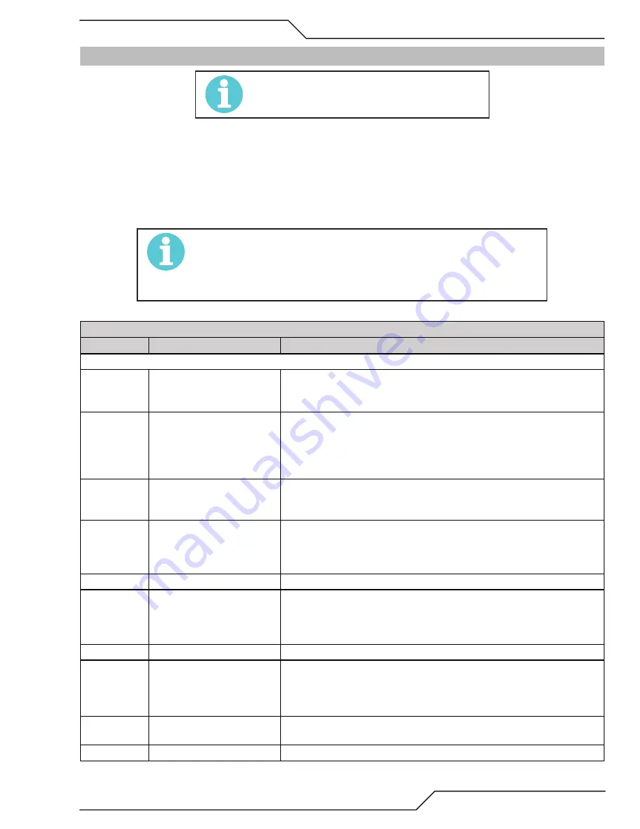
4.07 Power Supply Status Codes
NOTE!
See the Appendix for Advanced Troubleshooting
On start-up and during operation, the power supply control circuitry performs various tests. If the circuitry detects a condition
requiring operator attention, the status display on the front panel shows a 3 digit number code preceded by either letter “E” (cur-
rently active fault) or letter “L” (last or latched fault) meaning a fault occurred stopping the process but is not currently active.
Some conditions can be active indefinitely, while others are momentary. The power supply latches momentary conditions; some
momentary conditions can shut down the system. The indicator may show multiple conditions in sequence; it is important to
recognize all possible conditions that may be displayed.
NOTE!
There are no Group 5 (500) numbered status codes with the GCM 2010 system.
These tables cover units up to 400A, Lower current units won’t have all the
inverter sections referred to in the Group 2. However codes for those sections
should not appear.
CCM Status Code
Code
Message
Remedy / Comments
Group 1 -- Plasma Process
101
Plasma Disabled
Plasma Enable Off ; Disable activated on GCM 2010 or external SW disabled
(CNC); CCM TB1-1&2 jumper missing; 40 circuit ribbon cable from Relay
PCB to CCM disconnected or defective;
102
Pilot Ignition Failure
Pilot did not start within 15 seconds. Torch consumable parts worn? Ensure
correct process selected or manual setting including current control setting
matches consumables; Plasma pressure too high; Defective Arc Starter;
Defective Pilot PCB; defective Inverter section 1A. Ribbon cables reversed on
INV1 sections 1A and 1B.
103
Lost Pilot
Pilot went out while Start active. Torch consumable parts worn? Ensure cut
process or current control setting setting matches consumables; Plasma
pressure too high;
104
Transfer Lost
Arc was transferred to work then went out while Start still active. Arc lost
contact with work (run off edge, over hole, etc.); Standoff too high; Ensure
cut process or manual settings (current control, gas pressures) matches
consumables;
105
Not used
Reserved for legacy product
106
Pilot Timeout, no Transfer
Must transfer from Pilot to Cutting Arc in 0.085 seconds (SW8-1 OFF) or 3
sec. (SW8-1 ON). Standoff too high or void in work under torch; Wrong cut
process selected or wrong manual settings (current control set too low or
wrong gas pressure).
107
Tip Saver Fault
Tip remained in contact with work in excess of 15 seconds. ( Pak200i).
108
Tip to Electrode voltage fault.
Tip voltage too close to electrode voltage; Torch consumable parts worn out;
Wrong consumables installed causing tip to electrode short; Wrong process
selected or wrong manual setting of plasma gas or cutting current.; Leak in
Plasma hose to torch; Defective Pilot PCB; Shorted torch body .
109
Part process not configured. Applies only to DFC 3000 Auto Gas Control. Select and load a cutting pro-
cess.
110
Devise Locked
DFC 3000: Process loading; wait until finished
Summary of Contents for Ultra-Cut 300 XT
Page 6: ...This Page Intentionally Blank...
Page 10: ...TABLE OF CONTENTS This Page Intentionally Blank...
Page 15: ...ULTRA CUT 400 XT Manual 0 5275 SAFETY INSTRUCTIONS 1 5 This Page Intentionally Blank...
Page 88: ...ULTRA CUT 400 XT OPERATION Manual 0 5275 This Page Intentionally Blank...
Page 106: ...ULTRA CUT 400 XT REPLACEMENT PARTS Manual 0 5275 This Page Intentionally Blank...
Page 114: ...ULTRA CUT 400 XT TORCH INFORMATION Manual 0 5275 This Page Intentionally Blank...
Page 139: ...ULTRA CUT 400 XT Manual 0 5275 APPENDIX A 25 Display PCB Test Points TP1GND TP2 5VDC TP3 24VDC...
Page 148: ...ULTRA CUT 400 XT APPENDIX Manual 0 5275 APPENDIX 17 Cap Bias Bottom PCB Layout Art A 11685_AB...
Page 150: ...ULTRA CUT 400 XT APPENDIX Manual 0 5275 APPENDIX 19 Suppressor PCB Layout Art A 11684_AB...
Page 201: ...ULTRA CUT 400 XT Manual 0 5275 APPENDIX A 87 This Page Intentionally Blank...
Page 213: ......


