background image


154 


Format: 

BMP, PNG  

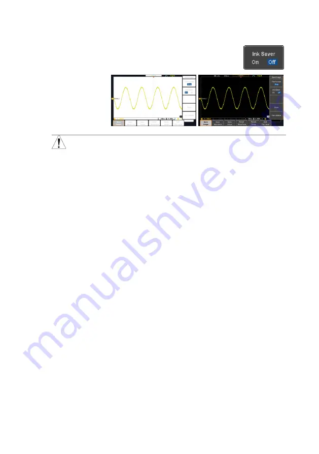
Ink Saver 

2.  To have a white background for 

image files, set 

Ink Saver

 to On.  


Ink Saver On 


Ink Saver Off 

Note 

*Each time the Hardcopy key is used to save 
waveforms or setup files, the files are saved into a 
new directory each time. The save directory is 
labeled ALLXXXX, where XXXX is a number that is 
incremented with each save. This directory is 
created in either the internal memory or to a USB 
flash drive.  


Summary of Contents for DCS-1000B SERIES

Page 1: ...INSTRUCTION MANUAL DIGITAL STORAGE OSCILLOSCOPE DCS 1000B SERIES DCS 1072B DCS 1102B DCS 1054B DCS 1074B DCS 1104B B71 0463 01...

Page 2: ...When copying the part or all of contents of this instruction manual seek the copyright holder In addition the specifications of the product and the contents of this instruction manual are subject to c...

Page 3: ...nt 24 2 2 1 Measurement Items 24 2 2 2 Add Measurement 27 2 2 3 Remove Measurement 28 2 2 4 Gated mode 29 2 2 5 Display All mode 29 2 2 6 High Low Function 30 2 2 7 Statistics 31 2 2 8 Reference Level...

Page 4: ...lly 65 3 4 6 Play Pause 67 3 5 Vertical View Channel 69 3 5 1 Move Waveform Position Vertically 69 3 5 2 Select Vertical Scale 69 3 5 3 Select Coupling Mode 70 3 5 4 Input Impedance 70 3 5 5 Invert Wa...

Page 5: ...Data Logger Option 124 4 6 Using the Digital Filter Option 126 4 7 Remote Disk 127 5 SAVE RECALL 130 5 1 File Format Utility 130 5 1 1 Image File Format 130 5 1 2 Waveform File Format 130 5 1 3 Sprea...

Page 6: ...ocket Server 157 8 1 4 USB Functionality Check 158 8 1 5 Socket Server Functionality Check 158 9 MAINTENANCE 163 9 1 1 How to use SPC function 163 9 1 2 Vertical Accuracy Calibration 163 9 1 3 Probe C...

Page 7: ...In this case if the product is incorrectly used in that part a serious danger may be brought about on the user s body or the product To use the part with this pictorial indication be sure to refer to...

Page 8: ...n 125VAC Accordingly you must change the power cord if you want to use the product at the power supply voltage higher than 125VAC If you use the product without changing power cord to 250VAC rated one...

Page 9: ...mmable or explosive gas or steam is generated or stored may result in an explosion and fire Do not operate the product in such an environment Also use in and around a place where a corrosive gas is ge...

Page 10: ...t and other connected device The following parts are connected to the chassis Probe for each channel and ground side of the input BNC connector Grounding conductor of the accessory 3 core power cord G...

Page 11: ...ons stable For consultation about the product calibration ask us or your local dealer Daily Maintenance When you clean off the dirt of the product covers panels and knobs avoid solvents such as thinne...

Page 12: ...cope for first time use The Set Up section also includes a starter on how to use this manual effectively 1 1 Main Features Model name Frequency bandwidth Input channels Real time Sampling Rate DCS 105...

Page 13: ...imizes the acquisition memory to selectively capture only the important signal details Up to 29000 successive waveform segments can be captured with a time tag resolution of 4ns Waveform Search Allows...

Page 14: ...Digital Volt Meter app Digital Filter High or low pass digital filter for analog inputs Optional Function Part number Description Segment Segment memory Function Search Search Function Bus Bus trigger...

Page 15: ...zontal controls Menu key Vertical controls Side menu keys 2ch Model VARIABLE POSITION HORIZONTAL TRIGGER LEVEL PUSH TO ZERO PUSH TO ZERO SCALE Measure Display Cursor Help App Save Recall Acquire Utili...

Page 16: ...ble or option from a menu use the side menu keys on the side of the panel See page 14 for details Digital Storage Oscilloscope GDS 2202E 200 MHz 1 GS s Visual Persistence Oscilloscope Side menu keys B...

Page 17: ...the trigger horizontal scale and vertical scale Run Stop Key Run Stop Press to Freeze Stop or continue Run signal acquisition The run stop key is also used to run or stop Segmented Memory acquisition...

Page 18: ...oints of interest when using the search function Optional function Trigger Controls The trigger controls are used to control the trigger level and options Level Knob LEVEL Used to set the trigger leve...

Page 19: ...for parallel and serial bus UART I 2 C SPI CAN LIN configuration Channel Inputs CH1 Accepts input signals Input impedance 1M Capacitance 16pF CAT I 300V USB Host Port 2V TypeA 1 1 2 0 compatible Used...

Page 20: ...ST BE CONNECTED TO GROUND Ser No Label Calibration Output Outputs the signal for vertical scale accuracy calibration USB Device Port The USB Device port is used for remote control LAN Ethernet Port Th...

Page 21: ...k Channel 4 Green Bus Waveforms Shows the bus waveforms for serial buses The values are displayed in hex or binary Channel Indicators The channel indicators show the zero volt level of the signal wave...

Page 22: ...ak detect mode Average mode For acquisition details see page 46 Signal Frequency Shows the trigger source frequency Indicates the frequency is less than 2Hz lower frequency limit Trigger Configuration...

Page 23: ...Default key on the front panel For details see page 141 1 3 3 First Time Use Background This section describes how to connect a signal adjust the scale and compensate the probe Before operating the D...

Page 24: ...PUSH TO ZERO PUSH TO ZERO SCALE POWER CH1 CH2 CH3 CH4 2 V 1M W 16pF Measure Display Cursor Help Test Save Recall Acquire Utility Autoset Run Stop Single Default Select Search Set Clear Zoom CH 1 CH 2...

Page 25: ...ng a menu key refers to the keys directly below or beside any menu icons or parameters When the user manual says to toggle a value or parameter press the corresponding menu item Pressing the item will...

Page 26: ...crease a variable Example 1 1 2 3 1 Press a bottom menu key to access the side menu 2 Press a side menu key to either set a parameter or to access a sub menu 3 If accessing a sub menu or setting a var...

Page 27: ...se the Variable knob to edit the value Toggling a Menu Parameter 1 1 Press the bottom menu key to toggle the parameter Reduce Side Menu 1 2 To reduce the side menu press the corresponding bottom menu...

Page 28: ...e Display Cursor Help Test Save Recall Acquire Utility Autoset Run Stop Single Default Select Search Set Clear Zoom CH 1 CH 2 CH3 CH4 M R B Menu 50 Force Trig 1 Remove All Menus 1 Press the Menu Off k...

Page 29: ...Clear Zoom CH 1 CH 2 CH3 CH4 M R B 2 1 4 Built in Help The Help key accesses a context sensitive help menu The help menu contains information on how to use the front panel keys Panel Operation 1 Pres...

Page 30: ...el press a channel key When activated the channel key will light up The corresponding channel menu will also appear CH1 CH1 Each channel is associated with the color shown beside each channel s VOLT D...

Page 31: ...reen Mode will fit the waveform to the best scale including any DC components offset AC priority mode will scale the waveform to the screen by removing any DC component Panel Operation 1 Connect the i...

Page 32: ...n Freeze Waveform using the Run Stop Key Press the Run Stop key once The Run Stop key turns red The waveform and signal acquisition freezes Stop Run Stop Run Stop To unfreeze press the Run Stop key ag...

Page 33: ...from the bottom menu will also reset the horizontal position Acquire As the waveform moves the display bar on the top of the display indicates the portion of the waveform currently shown on the displa...

Page 34: ...Scale For more detailed configuration see page 69 Set Vertical Position To move the waveform up or down turn the vertical position knob for each channel POSITION PUSH TO ZERO Push the vertical positi...

Page 35: ...2 2 1 Measurement Items V I Measurements Time Meas Delay Meas Overview FPREShoot RPREShoot FOVShoot ROVShoot Cycle Area Area Cycle RMS RMS Cycle Mean Mean Low High Amplitude Min Max Pk Pk Frequency Du...

Page 36: ...ithin the first cycle found in the gated region RMS The root mean square of all data samples specified by the Gating option Cycle RMS The root mean square value is calculated for all data samples with...

Page 37: ...pulse width Duty Cycle Ratio of signal pulse compared with whole cycle 100x Pulse Width Cycle Pulses Measures the number of positive pulses Pulses Measures the number of negative pulses Edges Measures...

Page 38: ...rence of two signals calculated in degrees 360 x t2 t1 Note The in built help system can be used to see detailed automatic measurement definitions 2 2 2 Add Measurement The Add Measurement function al...

Page 39: ...log inputs yellow CH1 blue CH2 pink CH3 green CH4 Choose a Source The channel source for measurement items can be set either before or when selecting a measurement item 5 To set the source press eithe...

Page 40: ...ting from the bottom menu 3 Choose one of the gating modes from the side menu Off full record Screen Between Cursors Cursors On Screen If Between Cursors is selected the cursor positions can be edited...

Page 41: ...27 instead 2 2 6 High Low Function Background The High Low function is used to select the method for determining the value of the High Low measurement values Auto Automatically chooses the best high...

Page 42: ...ettings from the side menu High Low Settings Histogram Min Max Auto Restore Default High Low Settings To return to the default High Low settings press Set to Defaults 2 2 7 Statistics Background The S...

Page 43: ...m the mean The standard deviation equals the squared root of the variance value Measuring the standard deviation can for example determine the severity of jitter in a signal The number of samples used...

Page 44: ...ference level Mid Ref Sets the middle reference for the first and second waveforms Low Ref Sets the low reference level Panel Operation 1 Press the Measure key Measure 2 Press Reference Levels from th...

Page 45: ...selected 3 When the H Cursor is selected repeatedly pressing the H Cursor key or the Select key will toggle which cursor is selected OR Select Range Description Left cursor movable right cursor posit...

Page 46: ...ess Set Cursor Positions As 100 Example Horizontal cursors FFT FFT cursors can use different units For FFT details see page 41 Cursor Hor position dB Voltage Cursor Hor Position dB Voltage Delta diffe...

Page 47: ...een cursors Example Horizontal cursors 2 3 2 Use Vertical Cursors Panel Operation Range 1 Press the Cursor key twice Cursor x2 2 Press V Cursor from the bottom menu if it is not already selected 3 Whe...

Page 48: ...r 1 cursor 2 Voltage Current cursor1 cursor2 Delta difference between cursors dV dt or dI dt 5 Use the Variable knob to move the cursor s up or down VARIABLE Select Units 6 To change the units of the...

Page 49: ...ursor1 cursor2 Delta difference between cursors d dt Example Horizontal cursors Vertical cursors XY Mode XY mode cursors measure a number of X by Y measurements Cursor Rectangular polar co ordinates p...

Page 50: ...Adds the amplitude of two signals Source CH1 4 Ref1 4 Subtraction Extracts the amplitude difference between two signals Source CH1 4 Ref1 4 Multiplication Multiplies the amplitude of two signals Sour...

Page 51: ...the Position key from the side menu and use the Variable knob to set the position Range 12 00 Div 12 00 Div To change the unit div settings press Unit div then use the Variable knob to change the unit...

Page 52: ...Frequency resolution Good Amplitude resolution Not good Suitable for Frequency measurement on periodic waveforms Rectangular FFT Window Frequency resolution Very good Amplitude resolution Bad Suitabl...

Page 53: ...then use the Variable knob Range 12 00 Div 12 00 Div To select the vertical scale of the FFT waveform press Vertical until the dB or voltage parameters are highlighted and then use the Variable knob...

Page 54: ...tion to the expression Function Intg Diff log Ln Exp Sqrt Abs Rad Deg Sin Cos Tan Asin Acos Atan Variable Adds a user specified variable to the expression Source CH1 4 Ref1 4 Operator Adds an operator...

Page 55: ...pression entry area 6 Use the Variable knob and Select key to create an expression Use the Variable knob to highlight a source function variable operator figure or measurement in orange Press the Sele...

Page 56: ...of the selected digit 3 Press Exponent Use the Variable knob to set the exponent of the variable 4 Press Go Back to finish editing VAR1 or VAR2 Vertical Position and Scale 1 Press Unit div and use the...

Page 57: ...airs for each acquisition interval bucket are used This mode is useful for catching abnormal glitches in the signal Average Multiple acquired data is averaged This mode is useful for drawing a noise f...

Page 58: ...ving the phase relationship between waveforms Connection 1 Connect the signals to Channel 1 X axis and Channel 2 Y axis or Channel 3 X2 axis and Channel 4 Y2 axis CH3 CH2 CH1 CH4 Y X X2 Y2 2 Make sure...

Page 59: ...rizontally Channel 2 knob moves the X Y waveform vertically Similarly the X2 and Y2 axis can be positioned using the channel 3 and channel 4 vertical position knobs POSITION CH1 POSITION CH2 The horiz...

Page 60: ...ed when the record length is changed 3 2 Segmented Memory Acquisition Option The advanced segmented memory utility allows the scope memory to be divided into different segments Each time the scope is...

Page 61: ...ed into segments to increase the number of events that can be effectively captured with the same acquisition memory Also notice that the scope doesn t need to rearm the trigger between each segment th...

Page 62: ...Set the Number of Segments Note Before the Segment function can be used set the trigger settings as appropriate for the signal you wish to use The number of segments that can be used depends wholly on...

Page 63: ...9 for configuring the trigger settings Run Segments 1 Toggle Segments On from the bottom menu 2 Toggle Segments Run from the bottom menu 3 The scope will automatically start acquiring segments The pro...

Page 64: ...4 in the section above when the segmented acquisition has completed 3 2 4 Navigate Segmented Memory Background After the segmented memory acquisitions have been captured you can navigate through each...

Page 65: ...d through to the last segment pressing the Play Pause key again will play through each segment again in reverse order 3 2 6 Segment Measurement Background The Segmented memory function can be used in...

Page 66: ...tic measurement results are listed A maximum of 8 automatic measurements can be used with this function Note To use automatic measurements with the segmented memory automatic measurements must first b...

Page 67: ...t list press Source and select the source channel for measurement Range CH1 CH4 Statistics Results This function will bin the measurement results of the selected automatic measurement into a user defi...

Page 68: ...rom the bottom menu Note This key will only be available in the Stop mode 2 Press Segments Info 3 A table showing all general setting information for the segmented memory acquisitions is shown on the...

Page 69: ...t 4 Press Start from the side menu and use the Variable knob to scroll to the segment of Start 5 Press End from the side menu and use the Variable knob to scroll to the segment of End 6 Press Go Back...

Page 70: ...ect a number or letter Press Back Space to delete a character 9 Press Save Now to save the file The filename need not have been edited to save the file 10 There are two types of waveform data Fast CSV...

Page 71: ...Both the sampled dots and the connecting line are displayed Example Vectors Dots 3 3 2 Set the Level of Persistence Background The persistence function allows the DCS 1000B to mimic the trace of a tra...

Page 72: ...ity 3 To set the waveform intensity press Waveform Intensity and edit the intensity Range 0 100 Example Waveform Intensity 50 Waveform Intensity 100 Graticule Intensity 4 To set the graticule intensit...

Page 73: ...key Display 2 Press Graticule from the bottom menu 3 From the side menu choose the graticule display type Full Shows the full grid X and Y axis for each division Grid Show the full grid without the X...

Page 74: ...splay mode 3 4 1 Move Waveform Position Horizontally Panel Operation The horizontal position knob moves the waveform left right As the waveform moves a position indicator on the on the top of the disp...

Page 75: ...se Run Mode In Run mode the memory bar and waveform size keep their proportion When the timebase becomes slower roll mode is activated if the trigger is set to Auto Stop Mode In Stop mode the waveform...

Page 76: ...side of the display to the left Automatically selected when the timebase sampling rate is slow Timebase 100ms div Trigger all modes Roll mode Select Roll Mode Manually 1 Press the Trigger Menu key Me...

Page 77: ...ontal Scale To change the horizontal scale press Horizontal Time Div and use the Variable Position knob The scale will be shown on the Horizontal Time Div icon VARIABLE Zoom To increase the zoom range...

Page 78: ...press the Zoom key again Zoom 3 4 6 Play Pause Background The Play Pause key can be used to play through signals in the Zoom mode Note If the Segmented memory function is turned on pressing the play...

Page 79: ...ontal position knob to control the scroll speed Turning the Horizontal knob determines the speed and direction of the scrolling Speed Left Speed Right POSITION PUSH TO ZERO Reset the Zoom Position To...

Page 80: ...ical position is shown in the Position Set to 0 soft key 4 To change the position press Position Set to 0 to reset the vertical position or turn the vertical position knob to the desired level CH1 POS...

Page 81: ...aveforms mixed with DC signals Ground coupling mode The display shows only the zero voltage level as a horizontal line Example Observing the AC portion of the waveform using AC coupling DC coupling AC...

Page 82: ...om the side menu Depending on the bandwidth of the oscilloscope Range 70MHz models Full 20MHz 100MHz models Full 20MHz Example BW Full BW Limit 20MHz 3 5 7 Expand by Ground Center Background When the...

Page 83: ...will expand from the center of the screen The ground level will suit to match the signal position Or from the upper or lower edge of the screen if the ground level is off screen Expand by Ground Expa...

Page 84: ...ob to set the attenuation Alternatively press Set to 10X Range 1mX 1kX 1 2 5 step Note The attenuation factor adds no influence on the real signal It just changes the voltage current scale on the disp...

Page 85: ...Start of Frame The Start bit is shown as an open bracket Stop Bit End of Frame The Stop bit is shown as a closed bracket Data Data packets frames can be shown in Hex or Binary The color of the bus da...

Page 86: ...C CAN and LIN Each interface is fully configurable to accommodate variations in the basic protocols Each input can be displayed as binary hexadecimal or ASCII An event table can also be created to ai...

Page 87: ...level Word size Bit order Trigger On SS Active MOSI MISO MOSI MISO CAN The CAN Controller Area Network bus is a 2 wire message based protocol Inputs CAN Input Threshold CAN Input Configuration Signal...

Page 88: ...age differential signals with active high signaling Universal Asynchronous Receiver Transmitter UART or RS 232 driver receiver ICs commonly used for embedded applications typically use active high sig...

Page 89: ...FF 3 6 2 3 I2 C Serial Bus Interface The I 2 C bus is a 2 wire interface with a serial data line SDA and serial clock line SCLK The I 2 C protocol supports 7 or 10 bit addressing and multiple masters...

Page 90: ...erial peripheral interface SPI is a full duplex 4 wire synchronous serial interface The 4 signals lines Serial clock line SCLK slave select SS Master output slave input MOSI or SIMO and the Master inp...

Page 91: ...ing edge SS Active High Active Low Word Size 4 32 bits Bit Order MS First LS First 3 6 2 5 CAN Serial Bus Interface The controller area network CAN bus is a half duplex 2 wire synchronous serial inter...

Page 92: ...rate of the bus The bit rate is usually tied to the bus length 3 Press Bit Rate from the bottom menu and set the bit rate Bit Rate 10kbps 20kbps 50kbps 125kbps 250kbps 500kbps 800kbps 1Mbps 3 6 2 6 L...

Page 93: ...bps 19 2kbps LIN Standard V1 x V2 x Both Include Parity Bits with Id On Off 3 6 2 7 Bus Encoding Background The bus that is displayed on the screen or in the event tables can be set to either hex or b...

Page 94: ...20mV 500mV Div 27V 2mV Div 508mV 200mV Div 5 8V 1mV Div 504mV 100mV Div 5 4V 3 6 3 1 Serial Bus Event Tables Background The serial bus event tables list when each data event on the bus occurred The da...

Page 95: ...Detail event table Save Event Table 1 To save the event table press Save Event Table The Event table will be saved to the current file path in a CSV format See page 86 for details Use the variable kno...

Page 96: ...ess Data at cursor position Select cursor Note Data Detail is only available with the 1 2 C bus Example SPI Event table Time of trigger MOSI MISO Select cursor Example CAN Event table Time of trigger...

Page 97: ...bered sequentially from 0000 to 9999 For example the first event table will be saved as Event_Table0000 CSV the second as Event_Table0001 CSV and so on Event Table Data Each event table saves a timest...

Page 98: ...on the left hand side of the display Panel Operation 1 To add a label to the bus press Edit Labels from the Bus menu 2 To choose a preset label Press User Preset from the side menu and choose a label...

Page 99: ...e label will appear next to the bus indicator Below the label ACK was created for the bus The bus is labeled as ACK Remove Label Press Label Display to toggle the label on or off 3 6 3 4 Using Cursors...

Page 100: ...sor Hor position Bus value s Cursor Hor position Bus value s 4 Use the Variable knob to move the movable cursor s left or right VARIABLE 3 7 Trigger The trigger configures the conditions for when the...

Page 101: ...y trigger example by time A B C D A Edge trigger B Delay Source C Delay time length D First triggering point Pulse Width Triggers when the pulse width of the signal is less than equal not equal or gre...

Page 102: ...gnal EXT TRIG AC Line AC mains signal Alternate Alternate between channel sources for the trigger source EXT Probe Probe trigger source Set the probe as either current or voltage Source Bus UART UART...

Page 103: ...Edge Delay Rise Fall trigger type only Trigger Level Edge Delay Level Adjusts the trigger manually using the Trigger LEVEL knob LEVEL PUSH TO ZERO Set to TTL 1 4V Sets the trigger level to 1 4V suitab...

Page 104: ...ow transition Negative polarity triggered on the low to high transition Polarity Pulse Runt Positive polarity positive runt Negative polarity negative runt Either either negative or positive runt Trig...

Page 105: ...l stays high or low for a designated amount of time Timer Timeout 4nS 10 0S Sets the amount of time that a signal must stay high or low for the timeout trigger 3 7 3 Setup Holdoff Level Background The...

Page 106: ...Use the side panel to select Auto or Normal triggering modes Range Auto Normal 3 7 5 Using the Edge Trigger Panel Operation 1 Press the trigger Menu key Menu 2 Press Type from the lower bezel menu 3...

Page 107: ...0V 5 screen divisions Set to TTL 1 4V Set to ECL 1 3V Set to 50 3 7 6 Using Advanced Delay Trigger Panel Operation 1 Set the edge trigger source This will set the initializing trigger for the delay so...

Page 108: ...vent press Event from the side menu and set the number of events Range 1 65535 events Set to Minimum 3 7 7 Using Pulse Width Trigger Panel Operation 1 Press the trigger Menu key Menu 2 Press the Type...

Page 109: ...nel Operation 1 Press the trigger Menu key Menu 2 Press the Type key from the lower bezel menu 3 Select Video from the side menu The video trigger indicator appears at the bottom of the display From l...

Page 110: ...ess the trigger Menu key Menu 2 Press the Type key from the lower bezel menu 3 Select Others Pulse Runt from the side menu The Pulse and Runt indicator appears at the bottom of the display From left p...

Page 111: ...rom the lower bezel menu 3 Select Others Rise and Fall from the side menu The Rise and Fall indicator appears at the bottom of the display From left slope source high low threshold threshold level cou...

Page 112: ...gger type threshold level coupling 4 Press Source from the lower menu Use the side menu to select a source Range Channel 1 4 EXT Ext Probe Volt Current Attenuation 1mX 1kX AC Line 5 Press Coupling fro...

Page 113: ...set to UART Panel Operation 1 Set the Bus to UART in the bus menu Page 77 2 Press the Trigger Menu key Menu 3 Press Type from the bottom menu 4 Press Others from the side menu and select Bus The Trigg...

Page 114: ...CII characters for the equivalent Hex characters 00 to FF 3 7 12 2 I2 C Bus Trigger Settings The I 2 C bus trigger conditions can be set at any time after the bus settings has been set to 1 2 C Panel...

Page 115: ...able knob to highlight a binary or hex digit and press Select Use the Variable knob to choose a value for the digit and press Select to confirm VARIABLE Binary 0 1 X don t care Hex 0 F X don t care Tr...

Page 116: ...Press Direction on the bottom menu and choose the direction from the side menu Direction Write Read Read or Write 3 7 12 3 SPI Bus Trigger Settings The SPI bus trigger conditions can be set at any tim...

Page 117: ...e knob to choose a value for the digit and press Select to confirm VARIABLE Binary 0 1 X don t care Hex 0 F X don t care 3 7 12 4 CAN Bus Trigger The CAN bus trigger conditions can be set at any time...

Page 118: ...Identifier from the side menu to set the identifier data To edit the identifier use the Variable knob to highlight a binary or hex digit and press Select Use the Variable knob to choose a value for th...

Page 119: ...ions 3 7 12 5 LIN Bus Trigger The LIN bus trigger conditions can be set at any time after the bus setting has been set to LIN Panel Operation 1 Set the Bus to LIN in the bus menu Page 81 2 Press the T...

Page 120: ...the side menu and choose the number of bytes for the data Bytes 1 8 Bytes 3 Press Data from the side menu to edit the triggering data To edit the data use the Variable knob to highlight a binary or he...

Page 121: ...el to determine events 3 8 1 Configuring Search Events Background Similar to configuring the trigger system the Search events must first be configured before they can be found Luckily the trigger syst...

Page 122: ...can be displayed on screen at once 3 8 2 Copying Search Event To From Trigger Events Background As the trigger system and search feature have similar settings their settings can be used interchangeab...

Page 123: ...e current event will always be centered on the display 3 8 4 Save Search Marks Background The search events can be saved to the graticule display allowing you to superimpose new search events Search e...

Page 124: ...be navigated to from in the same way that a normally saved search marker can Clear Search Event To clear a set search event use the search arrows to navigate to the event of interest and press the Set...

Page 125: ...hold level will be mirrored in the Threshold key Max Peak 1 10 Level 100db 100dB View Number of Peak Events To view the number of peak events set State Info to Mark The number of search events will be...

Page 126: ...port 2 Press Save Event Table The event table will be saved as PeakEventTbXXXX csv 2V Event Table CSV Format The format for the CSV file is the same as the event table displayed on the DCS 1000B scree...

Page 127: ...anel Operation 1 Press the Utility key Utility 2 Press Language on the lower menu 3 Select the language from the side menu Language selection may differ based on region and as such are not listed here...

Page 128: ...press Erase Memory again to confirm the process Pressing any other key will cancel erasing the memory 4 Press Erase Memory again 3 9 4 Probe Compensation Frequency Background The probe compensation ou...

Page 129: ...The DVM application displays a digital voltage meter readout that floats on the top left hand side of the screen Data Log The Data Log app will log waveform data and or screenshots at set intervals f...

Page 130: ...m boundary Boundary templates are automatically created from a source channel Boundary tolerances and violation conditions can be set Choose the Go_NoGo application from the APP menu See page 118 Set...

Page 131: ...NoGo conditions The waveform stops when the conditions are violated Ignore violations and continue to monitor the signal Each violation is counted 4 Press Go Back to return to the previous menu Set G...

Page 132: ...11 The Maximum Position tolerance will be saved to reference waveform R1 and the Minimum Position tolerance to R2 12 Press Go Back to return to the previous menu Start Go NoGo Press Enable to start t...

Page 133: ...to turn the reference waveforms off Using the Go NoGo Output To output the Go NoGo results to an external device the Go NoGo rear panel terminal open collector can be used The Go NoGo terminal will ou...

Page 134: ...app allows you to measure the AC RMS DC DC RMS Duty and frequency of an input signal This software is especially useful for those measurement applications that require both a DSO and a basic DVM to be...

Page 135: ...easurement mode for the meter 2 Press Mode and select the mode Mode AC RMS DC DC RMS Duty Frequency Turn On Off 3 Press DVM and toggle DVM on The DVM app will remain running in the background even if...

Page 136: ...erval time Interval Data 2secs 2mins Image 5secs 2mins 5 Press Duration and select the logging duration time Duration 5mins 100hrs 6 From the bottom menu press File Utilities and set the save file pat...

Page 137: ...xample Digital filter type or status High pass filter example Digital filter indicator Low pass filter example CH1 input 2Vpp 1kHz square wave low pass filter with 1kHz cutoff frequency CH2 input 2Vpp...

Page 138: ...ch channel to be the same When a setting is changed on one channel it is reflected on the other channels Note The digital filter settings will still apply to the relevant input signals after leaving t...

Page 139: ...for the username above Use the Up and Down soft keys navigate to each item in the form Use the Variable knob and Back Space soft key to enter characters for each item in the form Mount Unmount 4 To m...

Page 140: ...129 Example Remote disk drive Z drive...

Page 141: ...pe CH1 4 Input channel signal REF Reference waveform Math Math operation result page 39 Storage Location Wave1 Wave20 Waveform files stored to the internal memory Stored waveforms can be transferred t...

Page 142: ...enables the horizontal data points to be reconstructed such as trigger position etc Data is recorded as integers Note however that only fast CSV can be recalled to the internal memory Detailed CSV can...

Page 143: ...abel Probe type Probe ratio Vertical scale Vertical position Horizontal units Horizontal scale Horizontal position Horizontal mode SincET mode sampling mode Sampling period Horizontal old scale Horizo...

Page 144: ...orizontal Scale Math Source1 Operator Source2 Position Unit Div Math Off FFT Math Source Vertical Units Window Vertical position Horizontal position Advanced Math Expression VAR1 VAR2 Position Unit Di...

Page 145: ...1 In the example above the file label for channel 1 is displayed next to the channel indicator and is also displayed in the Edit Label menu The Ref_1 file label is shown next to the reference indicat...

Page 146: ...Space to delete a character Press Save Now to save the label and return to the previous menu To cancel the editing the label and return to the previous menu press Cancel Display Label To display the...

Page 147: ...Stored in ALLXXXX directories when the Hardcopy key is assigned to save Waveform Setup or All Note By default all filenames directories are named DSxxxx ALLxxxx where xxxx is a number starting from 00...

Page 148: ...o edit the name of the file 8 To edit the file name use the Variable knob to highlight a character VARIABLE Press Enter Character or the Select key to select a number or letter Press Back Space to del...

Page 149: ...he drive to the front panel USB port If a USB drive is not connected files can still be saved to the internal memory Front Panel 2 2 Press the Save Recall key from the front panel Save Recall 3 Press...

Page 150: ...as been pressed the file will be saved Note The file will not be saved if the power is turned off or the USB drive is taken out before the message ends File Utility To edit the internal memory or the...

Page 151: ...you will be able to edit the name of the file from the default DSxxxx filename 7 To edit the filename use the Variable knob to highlight a character VARIABLE Press Enter Character or the Select key t...

Page 152: ...ront panel Reference Waveform Internal memory Ref1 4 Current front panel Panel Setup DSxxxx set Internal memory S1 20 File system Disk USB Current front panel Waveform Data DSxxxx lsf DSxxxx csv CH1 C...

Page 153: ...Statistics Off Mean Std Dev Samples 2 High Ref 90 0 Mid Ref 50 0 Low Ref 10 0 Horizontal Scale 10us Div Position 0 000s Math Source1 CH1 Operator Source2 CH2 Position 0 00 Div Unit Div 200mV Math Off...

Page 154: ...call from From Wave1 20 From File File format Lsf Fast Csv Only files in the current file path will be available this includes files saved in the ALLxxxx directories Allxxxx csv files cannot be recall...

Page 155: ...y files in the current file path will be available 5 Press Recall Now to confirm recalling When completed a message appears at the bottom of the display Note The file will not be recalled if the power...

Page 156: ...ning R1 R4 ON will open the corresponding reference menu 3 If a reference waveform is ON but not active its reference menu can be opened by pressing the corresponding R1 R4 key from the bottom menu Ve...

Page 157: ...aveform details Details Sample Rate Record Length Date Edit Labels To edit labels for Setup files press Edit Labels For more details on editing labels see page 134 Save Reference Waveforms To save ref...

Page 158: ...memory to USB The File Utilities menu also sets the file path for saving and recalling files from the Save Recall menu 6 1 1 File Navigation The File Utilities menu can be used to choose files or to s...

Page 159: ...ve is used This saves you the hassle of setting the USB file path each time the USB flash drive is inserted into the scope 6 1 2 Create Folder Panel Operation 1 Press the Utility key Utility 2 Press F...

Page 160: ...eration 6 1 3 Rename File Panel Operation 1 Press the Utility key Utility 2 Press File Utilities from the bottom menu 3 Use the Variable knob and select key to choose a file to rename 4 Press Rename w...

Page 161: ...avigate the file system to choose a file 4 Press Delete to delete the selected file 5 Press Delete again to confirm the deletion 6 1 5 Copy File to USB Panel Operation 1 Connect a USB drive to the fro...

Page 162: ...o the USB drive Connect the USB drive to the front panel USB port Front Panel 2 2 Press the Utility key Utility 3 Press File Utilities from the bottom menu 4 Use the Variable knob and Select key to na...

Page 163: ...ctBridge printer to the USB device port on the rear panel LINE VOLTAGE AC 100 240V RANGE FREQUENCY 50 60Hz POWER MAX 30 Watts CAUTION TO AVOID ELECTRIC SHOCK THE POWER CORD PROTECTIVE GROUNDING DO NOT...

Page 164: ...ve to USB connect a USB drive to the front panel USB port otherwise the file will save to internal memory Front 2 2 Press the Utility key Utility 3 Press Hardcopy from the bottom menu 4 On the side me...

Page 165: ...Saver Off Note Each time the Hardcopy key is used to save waveforms or setup files the files are saved into a new directory each time The save directory is labeled ALLXXXX where XXXX is a number that...

Page 166: ...he rear panel device port 5 When the PC asks for the USB driver or Unknown device listed in Device Manager install TEXIO CDC inf attached CD 6 If the computer can not recognize the new hardware due to...

Page 167: ...r Off from the side menu Note IP addresses will automatically be assigned with DHCP BOOTP set to on For Static IP Addresses DHCP BOOTP should be set to off 6 Use the Up and Down arrows on the side men...

Page 168: ...direct two way communication with a client PC or device over LAN By default the Socket Server is off Configure Socket Server 1 Configure the IP address for the DCS 1000B Page 155 2 Press the Utility...

Page 169: ...Firmware version in the following format TEXIO DCS 1102B PXXXXXX V1 00 Note For further details about remote control and remote commands please see the DCS 1000B programming manual 8 1 5 Socket Serve...

Page 170: ...nt Automation 4 From the Configuration panel access My System Devices and Interfaces Network Devices 5 Right click Network Devices and select Create New Visa TCP IP Resource 4 5 6 Select Manual Entry...

Page 171: ...p will appear to tell you if a VISA socket session was successfully created 11 Click Next 10 11 8 9 12 Choose an alias for the socket connection if you like 13 Click Finish to finish the configuration...

Page 172: ...o send a remote command to the DCS 1000B 14 15 16 Click on the Configuration icon 17 Select the I O Settings tab 18 Mark the Enable Termination Character checkbox Make sure the termination character i...

Page 173: ...ommand drop box 22 Click on Query 23 The manufacturer model number serial number and firmware version will be displayed in the buffer For example TEXIO DCS 1202E PXXXXXX V1 00 20 21 22 23 Note For fur...

Page 174: ...ation 1 Press the Utility key Utility 2 Press System from the bottom menu 3 Press SPC from the side menu A message showing a brief introduction to SPC appears on the screen Note Disconnect all probes...

Page 175: ...e calibration for Channel 1 starts and ends automatically in less than 5 minutes A message is displayed when the calibration procedure has ended 9 Repeat the above step for Channel 2 3 and 4 when prom...

Page 176: ...oset Run Stop Single Default Select Search Set Clear Zoom CH 1 CH 2 CH3 CH4 M R B Menu 50 Force Trig x1 x10 X10 X1 CH1 2V 3 Press the CH1 key to activate CH1 CH1 4 Set the Coupling to DC from the bott...

Page 177: ...urement result FFT result Help contents from the display To clear automatic measurement results press the Measure key select Remove Measurement and choose Remove All See page 28 To clear individual me...

Page 178: ...dark on the background Use the Ink Saver function which reverses the background color For details see page 152 The accuracy does not match the specification Make sure the device is powered On for at l...

Page 179: ...lity key Utility 2 Press File Utilities from the bottom menu 3 Use the Variable knob to highlight the upgrade file 4 Press the Select key to begin the installation of the upgrade file Select 5 A messa...

Page 180: ...3 5ns Bandwidth Limit 20MHz 10 3 2 Common Specifications Vertical Sensitivity Resolution 8 bit 1mV 10V div Input Coupling AC DC GND Input Impedance 1M 16pF approx DC Gain Accuracy 1mV 4 full scale 2mV...

Page 181: ...e interval Real Time Sample Rate 1GSa s max Record Length Max 10Mpts Acquisition Mode Normal Average Peak Detect Single Peak Detection 2nS typical Average selectable from 2 to 256 X Y Mode X Axis Inpu...

Page 182: ...aveforms per second maximum Display Graticule 8 x 10 divisions Display Mode YT XY Interface USB Port USB 2 0 High speed host port X1 USB High speed 2 0 device port X1 Ethernet Port LAN RJ 45 connector...

Page 183: ...perating Cond Temperature 10 C 50 C Relative Humidity 85 10 3 3 2 For DCS 1102B 1104B Model GTP 100B 4 Position X10 Attenuation Ratio 10 1 Bandwidth DC 100MHz Input Resistance 10M when used with oscil...

Page 184: ...ave Recall Acquire Utility Autoset Run Stop Single Default Select Search Set Clear Zoom Menu 50 Force Trig POSITION POSITION VERTICAL MATH REF BUS PUSH TO ZERO PUSH TO ZERO M R B Digital Storage Oscil...

Page 185: ...7F Towa Fudosan Shin Yokohama Bldg 2 18 13 Shin Yokohama Kohoku ku Yokohama Kanagawa 222 0033 Japan http www texio co jp...

Reviews: