background image


EF 


EF/B 


User manual 


English

 Version 

10.0 

(valid for software V4.9 and higher) 


Series EuroFlow,  
Type EF  

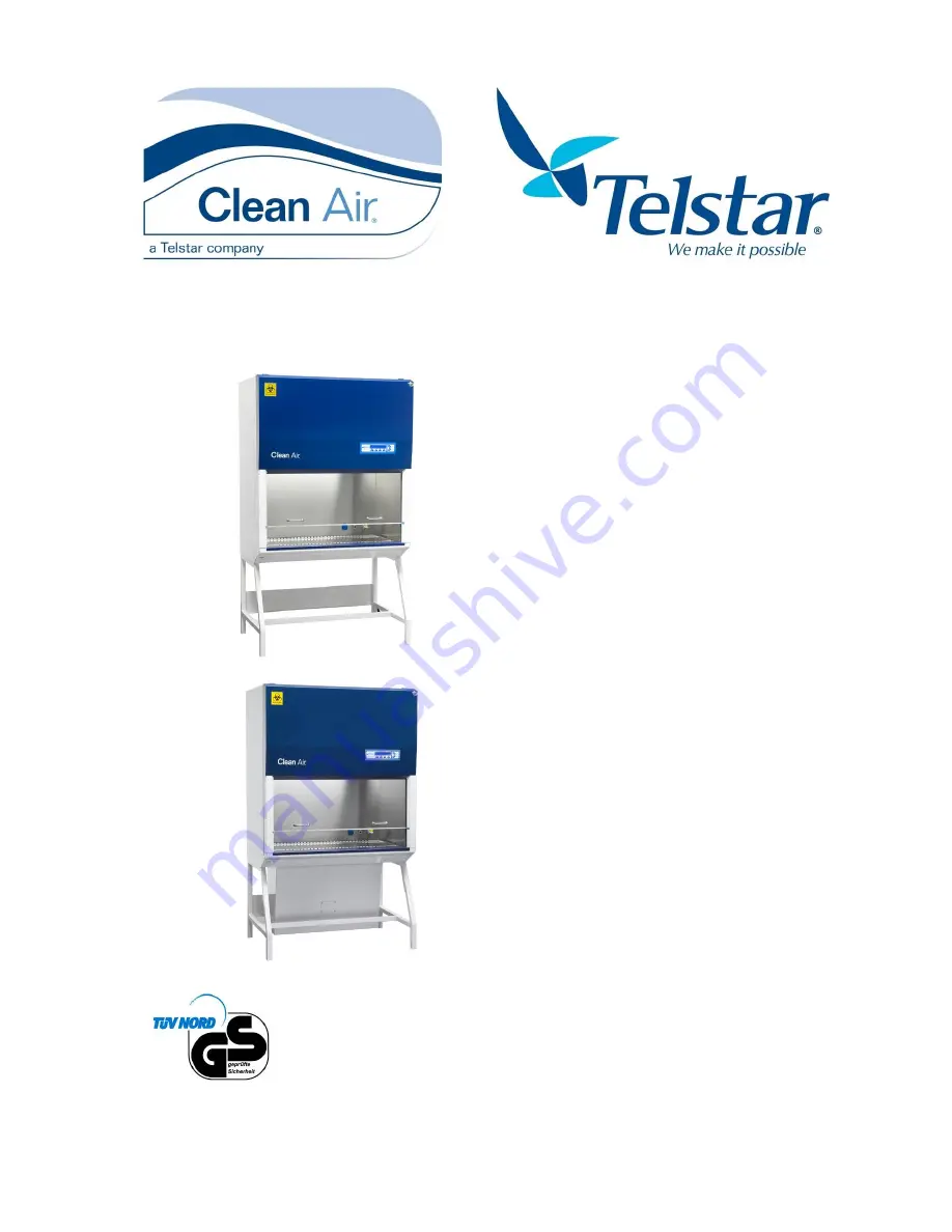
Biological Safety Cabinet Class II 

Type EF/B


Biological Safety Cabinet Class II 
 
 
Types: 
 
EF 4  
EF 5 
EF 6 
EF/B 4 
EF/B 6 


Offers protection for personnel, 
environment and product. 
 
 
Before using the safety cabinet, please read 
this manual carefully. The required 
instructions have to be carried out first. 
 
 
Clean Air Techniek B.V. 
Kuipersweg 37 
3449 JA Woerden 
Nederland 
t: +31 (0) 348 41 11 14 
f: +31 (0) 348 42 26 84 
e: [email protected] 
i: www.cleanair.eu


Summary of Contents for Clean Air EuroFlow Series

Page 1: ...inet Class II Types EF 4 EF 5 EF 6 EF B 4 EF B 6 Offers protection for personnel environment and product Before using the safety cabinet please read this manual carefully The required instructions hav...

Page 2: ...possibility to incorporate weighing systems microscopes etc or even build completely custom made cabinets Furthermore type EF and EF B are service friendly installations The safety cabinet is equippe...

Page 3: ...______________________15 4 5 Top hood ____________________________________________________________15 4 6 Worktop _____________________________________________________________15 4 7 Aerofoil___________...

Page 4: ...her alarms _________________________________________________________49 7 Cleaning_________________________________________________ 51 7 1 Cleaning the installation ____________________________________...

Page 5: ...microprocessor _______________________________________________84 Appendix X User code__________________________________________ 87 Activating the user code ___________________________________________...

Page 6: ...ulate Air the working area of the cabinet is free of particles This airflow is laminar the airflow has got no turbulence and has got a constant air speed Through the work opening C air is drawn into t...

Page 7: ...ow has got no turbulence and has got a constant air speed Through the work opening C air is drawn into the workspace inflow towards the front slots of the worktop This protects the personnel against p...

Page 8: ...rized persons Operating the installation The cabinet shall only be used by personnel which is familiar with the content regulations and warnings which are mentioned in this operating manual is familia...

Page 9: ...disrupt the airflow In addition all centrifuges themselves create an airflow which may fling particles out of the casing 7 When homogenizers are used in the installation all reservoirs have to be sec...

Page 10: ...o be evaluated and documented industrial safety act hazardous substances regulations Based on these findings the employees must be instructed 2 6 Explanation user safety symbols GENERAL DANGER You can...

Page 11: ...laining drawing Mount the support yoke Pos 1 to the reinforcement plate Pos 3 Mount optional feet support Pos 2 Item no 6 is used to position the cabinet to the support frame see 3 1 Placing the cabin...

Page 12: ...transported on a strong solid pallet After every transport the cabinet must be tested and calibrated GENERAL DANGER Be careful High center of gravity crossover point 3 3 Dismantling Disposal For dism...

Page 13: ...EuroFlow EF and EF B Biological Safety Cabinet UM EFAB EN10 doc 13 4 Product description Figure 3 Sectional view EF Figure 4 3D view EF Figure 5 Sectional view EF B Figure 6 3D view EF B...

Page 14: ...pe plate Figure 3 Figure 4 Figure 5 and Figure 6 Pos 1 mentions instructions that are important for the connection of the biological safety cabinet See Appendix VIII Stickers on page 81 4 2 Short user...

Page 15: ...ard including engine control Additional option print If you wish to check one of these components you need to hinge the top hood To check the interface board the safety cover has to be taken away auth...

Page 16: ...lass H14 in accordance with EN1822 After assembling each filter will be tested separately according to EN 12469 2000 Annex D Through the topside of the cabinet the exhaust filter can be reached 4 13 S...

Page 17: ...2 General specifications on page 61 for details 4 18 Electronics The electronics Figure 3 Figure 4 Figure 5 and Figure 6 Pos 18 consist of Operational print positioned in the top hood behind the opera...

Page 18: ...oltage drops or filter pollution With an installation with a double exhaust HEPA filter an additional fan is built in The fan regulations are mounted behind the light hood 4 22 Optional Fittings Figur...

Page 19: ...h set The Bunsen burner can be plugged into the outlet with a short cable inside the work space The plug of the foot pedal can be inserted into an outlet The Bunsen burner can only operate when the ca...

Page 20: ...The UV light is meant for disinfection of the working surface of the safety cabinet When the UV light switches on the FL lighting switches off The UV light can only be switched on when the window is...

Page 21: ...tions on page 61 for electrical details The constructions of these may vary per country When the Biological Safety Cabinet has been switched off this function has to be activated each time via the swi...

Page 22: ...by putting the plug into a grounded socket that is easy accessible 5 2 Top hood sliding window The hinge slide window can be in several positions see Figure 8 Window positions The used example of the...

Page 23: ...e cleaned but also for placing large objects in the working area The window can only be hinged when the window is slit downwards on the aerofoil and when the locking pins are locked see Figure 12 and...

Page 24: ...window Figure 10 Hinge instructions Figure 11 Locking pins Figure 12 Hinge position Figure 13 Slide position Figure 14 Swivel blocks Figure 15 Hinge position Figure 16 Slide position After hinge actio...

Page 25: ...est line gives the description of the function key underneath I II III IV Cabinet switched off not safe Monday 11 06 33 MENU Socket Off Fixed keys Lighting ON OFF Work mode fan ON OFF Power save mode...

Page 26: ...window Put the window in the working position see marks on the installation 3 The fan starts Cabinet is in start up mode The alarm indicator light is red There is an acoustic alarm Push button To ack...

Page 27: ...hapter 9 2 on page 61 Measuring these most critical measured values directly under the window ensures that the overall average inflow velocity is according to the guidelines of the EN12469 2000 Annex...

Page 28: ...Push button When the cabinet is locked enter the user code To acknowledge this alarm push button Cabinet in power save mode not safe Downflow to low Inflow MENU Socket Off 2 Slide down the window onto...

Page 29: ...be switched off Enter the user code and push button Cabinet switched off Not Safe Monday 11 06 33 MENU Socket Off 5 8 Control UV optional The UV function is only visible if this option is installed an...

Page 30: ...supply optional The gas function is only visible if this option is installed and the cabinet is in work mode with no air alarms In all other cases the gas valve will automatically be switched off and...

Page 31: ...or maximum voltage and current fuses Switching socket on 1 Cabinet in work mode See 5 4 Starting up the cabinet on page 26 Cabinet in work mode Safe Monday 11 06 33 MENU Socket Off 2 The display shows...

Page 32: ...mode See 5 4 Starting up the cabinet on page 26 Push button Menu Cabinet in work mode Safe Monday 11 06 33 MENU Socket Off 2 Push button A A Hour counter information B Status cabinet C Settings A B C...

Page 33: ...or starting menu Set up 7 days clock UV Cabinet in work mode See 5 4 Starting up the cabinet on page 26 Push button Menu Cabinet in work mode Safe Monday 11 06 33 MENU Socket Off 1 Set up for 7 days c...

Page 34: ...e en ending time The value can be changed by pushing button or Acknowledge the setting with button Push 2x button Esc for starting menu See also the Example on page 34 Disable 2c By pushing on Disable...

Page 35: ...sc 2 Set up the UV 7 days clock Push button Clock for setting up the UV 7 days clock Push button Change for changing the start and end time The value can be changed by pushing button or Saturday UV on...

Page 36: ...utton Change Tuesday has to be changed into Wednesday UV starting time at midnight 00 00 and UV off at 06 00 The display shows Acknowledge the setting with button Push 2x button Esc for starting menu...

Page 37: ...clock 1 Cabinet in work mode See 5 4 Starting up the cabinet on page 26 Set up display for socket 7 days clock shows Push button Menu Push button A Push 2x button Acknowledge the setting with button...

Page 38: ...binet It is however not possible to switch off the cabinet itself automatically 1 Cabinet in work mode See 5 4 Starting up the cabinet on page 26 Push 5x button 1x Menu 1 x A and 3x Acknowledge the se...

Page 39: ...sc 6 Acknowledge the setting Acknowledge the setting with button Push 2x button Esc for starting menu For more days hours minutes walk again through the menu and confirm each time Set up actual time 1...

Page 40: ...nform service personnel In information status more details are given about Actual velocities alarm setting and fan settings Information about the installed options Sockets UV Information about Options...

Page 41: ...chapter 9 2 on page 61 Measuring these most critical measured values directly under the window ensures that the overall average inflow velocity is according to the guidelines of the EN12469 2000 Anne...

Page 42: ...up from Step 2 Installed options display shows Push button For explanation codes see Appendix IX Information installed options on page 84 Push button Esc for starting menu Installed Options 1 Socket p...

Page 43: ...e contact Clean Air B V Also check the site of Clean Air B V www cleanair eu products downloads for more detailed information about disinfection Depending on the code of the installation the safety ca...

Page 44: ...self is no disinfection Activating the user code See Appendix X User code on page 87 Factory adjustments 1 Cabinet in work mode See 5 4 Starting up the cabinet on page 26 Cabinet in work mode Safe Mon...

Page 45: ...net on page 26 Cabinet in work mode Safe Monday 11 06 33 MENU Socket Off 2 Testing of alarms display shows Push button and C Push 3x button Push button Enter service code Testing of alarms 0000 Enter...

Page 46: ...The cabinet will be switched on automatically 1 Cabinet in work mode See 5 4 Starting up the cabinet on page 26 Cabinet in work mode Safe Monday 11 06 33 MENU Socket Off 2 Change the language Push bu...

Page 47: ...sound pressure level of at least 10 dB A more than the sound pressure of the working cabinet See Appendix XI Required specifications on page 89 In one band of the Terz band analysis mentioned in the...

Page 48: ...f the cabinet which helps to find possible causes see 5 13 Information status cabinet on page 40 Downflow too low Downflow too low Figure 20 Product protecting downflow is too low Product protection b...

Page 49: ...ikely the fuse is broken Replace it with a new one If the alarm is still there contact your service organization To reset this alarm you must disconnect the power plug from the main voltage Communicat...

Page 50: ...n the alarm will not mute immediately The cabinet needs time to get the correct airflows In case the alarm is still present Stop working close the window and push button The cabinet goes into the savi...

Page 51: ...he worktop see 4 6 Worktop on page 15 the space under the worktop and drip trays regularly A 1 solution of Natriumdodecylsulfat SDS solution CAS no 151 21 3 in demineralised water could be applied for...

Page 52: ...and below side of the aerofoil see 7 1 Cleaning the installation on page 51 Clean all visible parts which are normally covered by the aerofoil see 7 1 Cleaning the installation on page 51 Place the a...

Page 53: ...fect the window with liquid Put on gloves Switch off the installation see 5 7 Turn off on page 28 Hinge the window open see 5 2 Hinge the window on page 22 Clean and if necessary disinfect the window...

Page 54: ...Cabinets contaminated with cytotoxics are normally cleaned with a 1 solution of Natriumdodecylsulfat SDS solution CAS no 151 21 3 in demineralised water as described in 7 1 Cleaning the installation...

Page 55: ...10 doc 55 Chloormethine Mechlorethamine 51 75 2 Dactinomycine 50 76 0 Estramustine 2998 57 4 0 1 N Natronloog Sodium Hydroxide CAS no 1310 73 2 Example 3 Cytotoxic CAS no Recommended cleaner Mitomycin...

Page 56: ...abinet Contact your service organization for advice Guideline for testing and maintenance given by Clean Air Techniek B V is every 12 months at least Validate the system on safety Check for correct fu...

Page 57: ...rements are printed on the type plate see 4 1 Type plate on page 14 and Appendix VIII Stickers on page 81 Figure 28 Supplies needed Procedure Switch on the installation Make sure that the window is in...

Page 58: ...e plastic bag inside the front aperture with your left hand Figure 31 Positioning the left hand in the plastic bag Figure 32 Positioning the plastic bag on the aerofoil Positioning the plastic bag on...

Page 59: ...d the worktop back in its position Remove the gloves and put them in the appropriate container 8 3 Replacing the Fluorescent light FL light When an FL light see 4 20 FL lighting on page 18 needs to be...

Page 60: ...e HEPA filters on page 74 Alarm tests see Appendix VII Alarm test procedure on page 79 Check visual if the air direction of the inflow is in direction of the front aperture and laminar over the whole...

Page 61: ...4 EF B 6 Front aperture work mode hxl mm 165x1190 165x1495 165x1800 165x1190 165x1800 Front aperture maximum height mm 350 350 350 350 350 Exteriors dimensions without support frame without exhaust h...

Page 62: ...acc EN 1822 First HEPA filter HEPA V pleats Type PB H14 H14 acc EN 1822 8 pieces HEPA V pleats Type PB H14 H14 acc EN 1822 12 pieces Performance EF 4 EF 5 EF 6 EF B 4 EF B 6 Sound level according to...

Page 63: ...5 230 3 15 Power sockets Pmax W 725 725 725 725 725 Power consumption in standby mode with light switched off excl maximum power socket P J s W I A 303 1 3 513 2 2 568 2 5 533 2 3 766 3 3 Power consum...

Page 64: ...1 6 1 6 F9 PCB A T 1 6 1 6 1 6 1 6 1 6 Fuses option board EF 4 EF 5 EF 6 EF B 4 EF B 6 F1 Optional fan A T Max 8 Max 8 Max 8 Max 8 Max 8 F2 Optional A T Max 8 Max 8 Max 8 Max 8 Max 8 F3 Charge curren...

Page 65: ...ot working Window not down Window completely downwards Gas equipment is not installed x Gas button is not visible on display Option gas is not installed UV option has to be programmed please contact y...

Page 66: ...ological Safety Cabinet UM EFAB EN10 doc 66 Appendix I Support frames EF EF B For every type of cabinet from the EF series and the EF B series a specific support frame is available Figure 35 Example o...

Page 67: ...control print is only available in version number 2 4 270307 or higher The disinfection software itself is no disinfection The Biological Safety Cabinet can work according to automatic disinfection so...

Page 68: ...officer or the responsible examiner can decide if this procedure is valid or not Additional standard operation procedures can be necessary The valid procedures for the disposal of possible contaminate...

Page 69: ...t within specifications and or when it is not possible to adjust the air velocity according the specifications For the first V shaped HEPA filters only relevant to the EF B class II cabinets the follo...

Page 70: ...sal procedure Removing the old downflow HEPA filter Decontaminate the cabinet Switch off the installation and plug out the power plug Put on the gloves and keep an extra pair ready for use Put on your...

Page 71: ...Appendix IV Efficiency test of the HEPA filters on page 74 Replacement of the exhaust HEPA filter For replacement of the exhaust HEPA filter the following procedure must be followed Supplies needed Pl...

Page 72: ...HEPA filter the following procedure must be followed Supplies needed Plastic bag with closure minimum measurement depends on the volume of the HEPA filter Gloves 4 pair for EF B 4 6 pair for EF B 6 S...

Page 73: ...inner side of the plastic bag Press the air out of the bag with its opening still in the working space Seal the plastic bag airtight Remove the plastic bag and place it in an appropriate container Rem...

Page 74: ...ements Efficiency test by means of a particle counter The downflow exhaust and first filter must have an efficiency of 99 995 A locally measured value can be a factor 10 higher 0 05 Efficiency test wi...

Page 75: ...point upstream concentration for the downflow filter as well as the exhaust filter is positioned under the work area Figure 37 Pos B and Figure 38 The downflow filter and the exhaust filter can be sc...

Page 76: ...biological safety officer or the responsible examiner can decide if this procedure is valid or not Additional standard operation procedures can be necessary The measurement of air velocities in the c...

Page 77: ...The minimal required value of the average inflow velocity measured at the top of the front aperture is given in chapter 9 2 on page 61 Measuring these most critical measured values directly under the...

Page 78: ...oFlow EF EF B Biological Safety Cabinet Clean Air Techniek B V UM EFAB EN10 doc 78 Appendix VI Lay out boards Interface board Figure 44 Interface board Control board Figure 45 Control board E010001 re...

Page 79: ...touched the fan returns to its work mode Alarm test procedure 1 Cabinet in work mode See 5 4 Starting up the cabinet on page 26 Push button Menu Push button C Cabinet in work mode Safe Monday 11 06 33...

Page 80: ...37 m s The fan speed is shown in tenths of percents 0 min and 1000 max 1 The average inflow velocity at the top of the front aperture is measured and can be read in the display The minimal required va...

Page 81: ...ticker cabinet type This sticker can be found on the outside underneath the cabinet For an example of the sticker see the picture underneath 2 Sticker filter type This sticker can be found behind the...

Page 82: ...ticker has to positioned in sight of the operator 8 Cytotoxic only EF B This sticker is delivered with the cabinet Depending on the work that is done on the cabinet the customer must decide whether th...

Page 83: ...s sticker is delivered with the cabinet Depending on the work that is done on the cabinet the customer must decide whether there are any Cytotoxic hazards or not In case of any Cytotoxic hazards the s...

Page 84: ...the airflow in the exhaust chamber In this case it is recommended to remove the exhaust hood or contact Clean Air Techniek B V for advice For the same reason the exhaust channel may not be obstructed...

Page 85: ...are factory adjustments and cannot be changed by the user Overview functions of relay K3 B1 B5 Alarm B1 B5 relay switching K3 on output J22 at the IO print B1 the K3 relay is activated if the main fan...

Page 86: ...th intervals To install alarm limits start from the menu as described in 5 13 Information about the installed options on page 41 The display only shows when the options are installed 1 Starting from s...

Page 87: ...is a special code to break the unknown or forgotten user code In that case enter code 2882 and the original pre installed code 0001 is valid again 1 Cabinet in work mode See 5 4 Starting up the cabin...

Page 88: ...Push button Menu and C Push 4x button Push button Enter actual user code Push button Enter the new valid user code Push button User code 0000 Enter code A Enter Esc Input user code New code 0000 Old c...

Page 89: ...12469 Annex A 6 Type test Yes Glass and front windows Laminated safety glass or UV resistant safety plastics EN 12469 Annex A 7 Type test Yes Glass and front windows Conform to EN 12100 1 2003 and 121...

Page 90: ...and front windows Laminated safety glass or UV resistant safety plastics DIN 12980 Chapter 6 Type test Yes Electrical safety Conform to EN 61010 1 DIN 12980 Chapter 11 Type test Yes Ergonomics Mainte...

Page 91: ...9S2R3L 15P6 610X1524X69 mm H14 acc EN 1822 Exhaust HEPA filter EF 5 1000606 AAF Astrocell A99C9S2R3 6P6 610X610X69 mm H14 acc EN 1822 Pre filter EF 5 1050001 G3 EN 779 Torsion spring EF 5 2700675 Cold...

Page 92: ...ll 6400010 Acrotronics F BK D 3940 ZG 10A PCB material All Duraver FR 4 according to UL94 Socket All Misc e g Mennekes Schuko Optional Gas vacuum tap All 2800013 2800048 Broen 1770 Gas valve All 28200...

Page 93: ...EuroFlow EF and EF B Biological Safety Cabinet UM EFAB EN10 doc 93 Appendix XIII Short user manuals Figure 49 Short user manual EF series Figure 50 Short manual EF B series...

Page 94: ...EuroFlow EF and EF B Biological Safety Cabinet UM EFAB EN10 doc 94 Appendix XIV TUV Low Pressure Mercury Lamps...

Page 95: ..._______________________ is in compliance with the following directives Machine Directive 2006 42 EC Low Voltage Directive 2006 95 EC Electromagnetic Compatibility Directive 2004 108 EC And declares f...

Page 96: ...EuroFlow EF and EF B Biological Safety Cabinet UM EFAB EN10 doc 96 Appendix XVI Memo...

Page 97: ...xhaust HEPA filter 6 7 F Factory adjustments 44 Fan 6 18 Feet Support 16 Fixed keys 25 FL light 59 FL lighting 18 Front panel 16 Function keys 25 G Gas connection 18 Gas supply off 30 Gas supply on 30...

Page 98: ...et up socket 7 days clock 37 Short user manual 14 93 Signals 25 Slide window 23 Sliding window 22 Socket off 31 Socket on 31 Sockets 21 Software Version 60 Standby mode 28 Starting up the cabinet 26 S...

Reviews: