Getting Started
6
P6467 High-Speed Probe Adapter Instruction Manual
Table 1: Factory Default Jumper Positions
P6467 Probe Jumper
Jumper Position
J1 (EXT/MSTR CLK)
MSTR CLK
J2 (NORM/DIV2)
DIV2
J3 (CLK A/MSTR CLK)
CLK A
J4 (DIV2/NORM)
DIV2
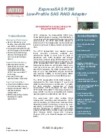
To set the clock jumpers on the Master Clock probe, you must remove the cover
from the probe. To remove the cover, remove the two screws on each side of the
probe. Figure 4 shows the locations of the jumpers on the probe. Note that it is
only necessary to configure the jumpers on the Master Clock probe.
CLKA/MSTR CLK
(J3)
EXT/MSTR CLK
(J1)
NORM/DIV2
(J4)
DIV2/NORM
(J2)
GND
THLD
THLD
ADJ
F2
F1
Figure 4: Clock Jumper Locations on the P6467 Probe
After determining the jumper locations on the probe, replace the probe cover and
continue with the following steps:
1. Refer to Figure 5 and connect the probe power cable to the probes (each
92A96 Module can power two P6467).
a. Bend the power cable near the connector as shown.
b. Insert the power connector into the connector socket.
Summary of Contents for 070-9176-00
Page 5: ......
Page 13: ...Service Safety Summary viii P6467 High Speed Probe Adapter Instruction Manual ...
Page 39: ...Operating Basics 24 P6467 High Speed Probe Adapter Instruction Manual ...
Page 45: ...Reference 30 P6467 High Speed Probe Adapter Instruction Manual ...
Page 49: ...Specifications 34 P6467 High Speed Probe Adapter Instruction Manual ...
Page 51: ......
Page 65: ...Adjustment Procedures 50 P6467 High Speed Probe Adapter Instruction Manual ...
Page 77: ...Replacable Parts 62 P6467 High Speed Probe Adapter Instruction Manual ...
Page 81: ...Appendix B P6467 Test Board 66 P6467 High Speed Probe Adapter Instruction Manual ...
Page 84: ......