


Operating Basics
DG2040 Data Generator
2Ć51
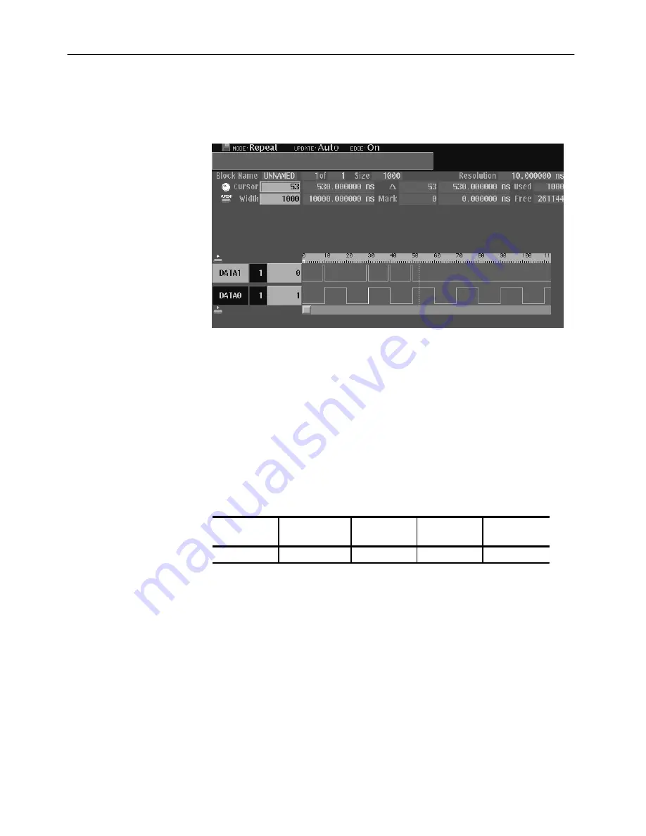
The edges to be controlled are highlighted. Figure 2-35 shows the created
patterns and highlighted edges.
Figure 2Ć35: Created pattern and highlighted edges
Follow the steps below to change the edge position:
4. Connect the DG2040 to the oscilloscope. Refer to Figure 2-25 on page 2-36.
5. Press the START/STOP button on the front-panel to start output.
6. Set the trigger to CH2 in the oscilloscope. Adjust the oscilloscope setting to
display the DATA0 pattern output.
7. Change the edge position.
Menubutton
Bottom button
popĆup menu
Side button
FrontĆpanel
button
APPLICATION Edge Control
Position Offset
8. Change the edge position with the general-purpose knob. Use the oscillo-
scope to verify that the edge was moved.
For example, when an output signal has been input from a function generator
(Tektronix AFG310) to the EDGE CONTROL INPUT on the DG2040 front
panel, you can continuously change the specified edge position.
Summary of Contents for DG2040
Page 1: ...User Manual DG2040 Data Generator 071 0257 04 This document supports firmware version 1 00...
Page 4: ......
Page 18: ...Preface xiv DG2040 Data Generator...
Page 19: ...Getting Started...
Page 20: ......
Page 32: ...Getting Started 1 12 DG2040 Data Generator...
Page 33: ...Operating Basics...
Page 34: ......
Page 87: ...Reference...
Page 88: ......
Page 152: ...Reference 3 64 DG2040 Data Generator...
Page 186: ...Reference 3 98 DG2040 Data Generator...
Page 187: ...Appendices...
Page 188: ......
Page 200: ...Appendix A Specifications A 12 DG2040 Data Generator...
Page 248: ...Appendix B Performance Verification B 48 DG2040 Data Generator...
Page 258: ...Appendix C Miscellaneous C 10 DG2040 Data Generator...
Page 259: ...Index...
Page 260: ......
Page 265: ......
Page 266: ......


