background image

Reference

DG2040 Data Generator

3Ć57

Make Sequence Menu

A sequence is a function to output blocked pattern data in a predetermined order
as specified in a sequence table. In the sequence table, repeat count, trigger wait,
event jump, and calling subsequences are used, as well as placing the blocked
patterns in a sequential order.

H

The blocked patterns are output in the line-numbered order defined in the
sequence table.

H

A patterned data or subsequence can be defined in each line in the sequence
table.

H

A line can be repeated on output from 1 to 65536 times or continuously.

H

A line can wait trigger event for output.

H

A line can be jumped to a specified line by the trigger of event signal.

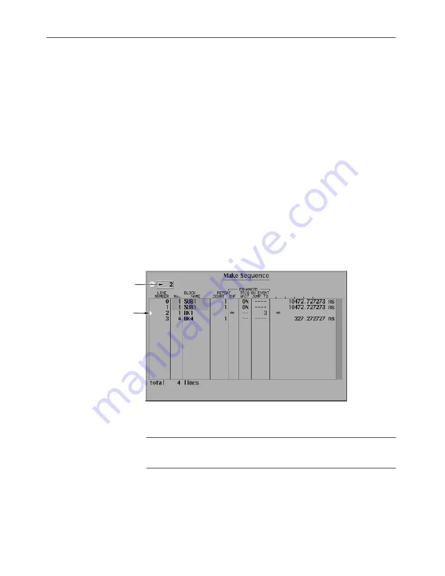
Figure 3-51 shows an example of a sequence. In this example, two subsequences
SUB1 waiting trigger event, a blocked pattern data BK1 to be infinitely repeated
and jumped to the line 3 on event signal, and blocked pattern data BK4 are
defined.

Line Pointer

Line number of

the current line

pointer position

Figure 3Ć51: Make Sequence menu and a sequence example

NOTE

. Enhanced columns in Figure 3-51 does not become effective unless the

run mode is not set to Enhanced. For enhanced mode, refer to Run Mode Menu
on page 3-74.

Summary of Contents for DG2040

Page 1: ...User Manual DG2040 Data Generator 071 0257 04 This document supports firmware version 1 00...

Page 2: ...ssued and pending Information in this publication supercedes that in all previously published material Specifications and price change privileges reserved Printed in Japan Sony Tektronix Corporation 5...

Page 3: ...tions This warranty shall not apply to any defect failure or damage caused by improper use or improper or inadequate maintenance and care Tektronix shall not be obligated to furnish service under this...

Page 4: ......

Page 5: ...of Operation 2 8 Data Structure Overview 2 10 Operating Modes Overview 2 12 Basic Menu Operations 2 13 Tutorials 2 26 Reference Reference 3 1 Edit Menu Screen 3 1 Menu Trees 3 3 Edit Menu Functions 3...

Page 6: ...teristics A 1 Certification and Compliances A 10 Appendix B Performance Verification B 1 Before Running the Performance Tests B 2 Self Tests B 5 Performance Tests B 7 Test Record B 43 Appendix C Misce...

Page 7: ...isplay format 2 19 Figure 2 13 Table display format 2 20 Figure 2 14 Binary display format 2 20 Figure 2 15 Numeric display format 2 21 Figure 2 16 Pattern data editing procedure 2 22 Figure 2 17 Seri...

Page 8: ...onfig menu 3 16 Figure 3 10 Settings pop up menu 3 18 Figure 3 11 Reference mark M display 3 19 Figure 3 12 Arrow button action display timing display 3 20 Figure 3 13 The Arrow button menu 3 21 Figur...

Page 9: ...menu 3 53 Figure 3 50 Edit Code Table menu 3 55 Figure 3 51 Make Sequence menu and a sequence example 3 57 Figure 3 52 Make Subsequence menu and a subsequence example 3 58 Figure 3 53 Example of a seq...

Page 10: ...chart B 13 Figure B 6 External reference input connections B 15 Figure B 7 Maximum operating frequency connections B 18 Figure B 8 Maximum operating frequency 1 B 20 Figure B 9 Maximum operating freq...

Page 11: ...menu functions 3 7 Table 3 3 Import parameters 3 11 Table 3 4 Export parameters 3 16 Table 3 5 Arrow button functions 3 21 Table 3 6 Pattern data display format 3 22 Table 3 7 Block cursor movement 3...

Page 12: ...ompliances A 10 Table B 1 Performance check disk files B 2 Table B 2 Required equipment B 3 Table B 3 Error codes B 6 Table B 4 Internal clock frequency accuracy B 10 Table B 5 High level output volta...

Page 13: ...ings To avoid fire or shock hazard observe all ratings and markings on the product Consult the product manual for further ratings information before making connections to the product Do Not Operate Wi...

Page 14: ...n injury hazard immediately accessible as you read the marking WARNING indicates an injury hazard not immediately accessible as you read the marking CAUTION indicates a hazard to property including th...

Page 15: ...l editing The Reference section provides detailed information about the functions and use of the DG2040 Data Generator s main menus The Appendices section provides product specifications performance v...

Page 16: ...each row When you are done executing the steps in one row move to the left end of the next row down and continue executing the listed steps until the end of the table H When steps require that you ma...

Page 17: ...e mail tm_app_supp tektronix com For product support outside of North America contact your local Tektronix distributor or sales office Service Support Contact your local Tektronix distributor or sales...

Page 18: ...Preface xiv DG2040 Data Generator...

Page 19: ...Getting Started...

Page 20: ......

Page 21: ...terns due to the external events The operating parameters the channel configuration and the pattern data are displayed or set using the graphic menu on the CRT monitor The menu has a tree structure an...

Page 22: ...have a low probability of occurrence or are difficult to generate H Constructs interactive digital simulation systems by using the sequence output external jump and tristate control functions H Uses...

Page 23: ...hipment becomes necessary Power Cord Options Table 1 1 lists the power cords available with the DG2040 Data Generator Table 1 1 Power cord options Option Description Tektronix part number A1 Europe 16...

Page 24: ...arted 1 4 DG2040 Data Generator Table 1 2 Power Cord Identification Plug Configuration Normal Usage Option Number North America Standard Europe A1 United Kingdom A2 Australia A3 North America A4 Switz...

Page 25: ...d accessories Tektronix part number DG2040 Data Generator User Manual 071 0257 XX DG2040 Data Generator Programmer Manual 071 0258 XX Performance Check Disk 3 5 inch 063 3121 XX GPIB Sample Program Di...

Page 26: ...able 012 0991 00 50 W SMA Cable 1 m 39 inches male 174 1341 00 50 W SMA Cable 2 m 21 inches male 174 0679 00 50 W SMA Cable 0 5 m 20 inches male 174 1427 00 SMA Precision Delay Cable 1 ns male 015 056...

Page 27: ...tallation refer to the General Safety Summary at the front of this manual for power source grounding and other safety information Verify that you have the correct operating environment CAUTION Damage...

Page 28: ...Fuse Cap Part Number 0 25 inch 1 25 inch UL 198 6 3 AG 6 A fast 250 V 159 0239 00 200 2264 00 5 mm 20 mm IEC 127 5 A T 250 V 159 0210 00 200 2265 00 NOTE The second fuse listed in the table above is...

Page 29: ...ly power to the standby circuit of the instrument by pushing the PRINCIPAL POWER SWITCH on the rear panel of the instrument Refer to Figure 1 1 NOTE After the instrument is installed leave the PRINCIP...

Page 30: ...s defined operating characteristics If all the diagnostic items have been completed without error the instrument displays the EDIT menu NOTE If the instrument chassis temperature is outside the specif...

Page 31: ...Service Center for repair or calibration attach a tag to the instrument showing the following information H The owner of the instrument with address H The name of a person at your firm who may be con...

Page 32: ...Getting Started 1 12 DG2040 Data Generator...

Page 33: ...Operating Basics...

Page 34: ......

Page 35: ...g information H An overview of the instrument controls and their functions H An overview of the DG2040 Data Generator hardware H Information on operations commonly performed on the instrument and how...

Page 36: ...nel can be varied from 1 0 ns to 1 0 ns If you use only one output connector for each channel you must terminate the other connector using an SMA termination Cancels the current operation and closes s...

Page 37: ...lues The knob icon displayed on the screen indicates that this knob controls the item The arrow buttons move the cursor They are also used for special functions that are described on the screen when e...

Page 38: ...t input signal CLOCK OUT Connector SMA connector provides an internal clock output signal If you use only one CLOCK OUT connector you must terminate the other connector using an SMA termination The RS...

Page 39: ...ppy disk drive to save and recall instrument patterns and for setting data CAUTION Data corruption on the floppy disk may occur if the eject button is pressed while the DG2040 Data Generator is writin...

Page 40: ...re 2 4 shows the display elements including bottom and side menus work area status lines and so on Also shown are a pop up menu and message box Table 2 1 describes each element in detail 1 2 3 4 5 6 7...

Page 41: ...en a bottom menu item is selected The topmost entry in the side menu displays either a label representing the side menu or the operation name for the confirmed item 2 15 4 Bottom menu When one of the...

Page 42: ...describes these hardware blocks to provide the background knowledge necessary to use the instrument effectively PLL Clock Clock Unit Pattern Control Circuit Pattern Memory Sequence Memory Output Chan...

Page 43: ...pecified by the user This unit includes a pattern control circuit pattern memory and sequence memory Pattern memory and sequence memory are high speed memories that hold the pattern data and sequence...

Page 44: ...2 2 Data structure terms Term Meaning Pattern data Basic data for patterns consisting of 2 bit words Memory size The number of pattern data words 360 words to 256 K words Group allocation Definitions...

Page 45: ...nnel states and other parameters These settings are collectively referred to as the setup data Since this data is associated with the pattern data it is handled together with the pattern data in opera...

Page 46: ...erating Modes Overview In the run modes pattern output is controlled by the pattern generation units pattern control circuit The DG2040 Data Generator supports four run modes repeat single step and en...

Page 47: ...mode may be slow when there is a large amount of data being edited In such cases it is more efficient to perform a number of edit operations and then update the output data in manual mode Basic Menu...

Page 48: ...vokes a lower level menu H Selects an item H The selected item changes each time a bezel button is pressed H A list is displayed and an item is selected from that list H Enables a numeric input H Exec...

Page 49: ...ng to whether items are selected or not and whether an item is valid or not as shown in Table 2 5 Table 2 5 Bottom menu elements Menu item Description Menu item in the unselected state The small box i...

Page 50: ...numeric values to be set using the numeric keys or the general purpose knob Menu items that cannot be used in the current instrument state Enter numeric values by using the front panel keypad or the...

Page 51: ...m the menu item field Figure 2 9 Numeric entry in a menu item field Numeric Input Example Table 2 7 shows how to change the clock frequency to 12 3 Hz when the value before entering the input state wa...

Page 52: ...e knob is used to increase or decrease the value of the digit indicated by the underscore Rotating the knob to the left decreases the value and rotating it to the right increases the value Figures 2 1...

Page 53: ...e effect of turning the general purpose knob by a factor of ten 3 Change the value by turning the general purpose knob You can display pattern data in one of four formats timing display table display...

Page 54: ...2 13 Figure 2 13 Table display format Binary Display Format The Binary display format shows the data bit states for each clock as 0 or 1 This is the basic display for digital signals and is an approp...

Page 55: ...ure 2 15 Numeric display format The different editing operations are selected from the EDIT Execute Action menu Press the front panel EXECUTE button to execute the selected operation Editing can be ac...

Page 56: ...ution Pattern data 2 1 3 4 Figure 2 16 Pattern data editing procedure Parallel Serial Editing The Numeric display format allows you to edit the data of every specified bit width in a selected data bit...

Page 57: ...rea cursor and the point cursor Figure 2 18 shows these cursors Knob Icon Cursor Window Width Window Cursor Window Value Point Cursor Area Cursor Scope Width Window Value Figure 2 18 Area and Point cu...

Page 58: ...the knob icon has been moved to the Cursor window with the front panel CURSOR button Text input is required to enter the names for data groups data blocks floppy disk files and other items When such...

Page 59: ...that would be difficult to recover Figure 2 20 shows the file deletion confirma tion message box Press the side menu OK button to execute the operation displayed in the box Press Cancel to cancel the...

Page 60: ...ions required to execute the instrument s basic functions Be sure that the DG2040 Data Generator is properly installed Refer to Installa tion on page 1 7 Refer to Power On on page 1 9 for power on ins...

Page 61: ...Pop up menu Side button Front Panel button Operation 1 Operation 2 Operation 3 Operation 4 Operation 5 Operation 6 For example set to xx with general purpose knob Operation 7 Menu Buttons Bottom Butto...

Page 62: ...create a pattern and then store the file 1 Clear the data memory Menu button Bottom button Pop up menu Side button Front panel button EDIT File New OK 2 Set up the environment by setting the pattern...

Page 63: ...pressing the front panel CURSOR button once or twice 0 ENTER Move the knob icon to the Width window in the upper left area of the screen by pressing the front panel CURSOR button once 1024 ENTER Press...

Page 64: ...h character in the file name using the general purpose knob and the up and down arrow buttons Press the EXECUTE button to insert the character in the file name The data in this procedure is saved in t...

Page 65: ...elect the file COUNT1 PDA from the file list using the general purpose knob OK 3 Select DATA1 as the area to be edited Menu Button Bottom Button Pop up Menu Side Button Front Panel Button Execute Acti...

Page 66: ...Button Pop up Menu Side Button Front Panel Button Execute Action Set scope OK 1 OK Set the block cursor to cover DATA1 using the up and down arrow buttons b Set the glitch width to be 1 Menu Button B...

Page 67: ...Button Move the knob icon to the Cursor window in the upper left of the screen by pressing the front panel CURSOR button once 35 ENTER EXECUTE 91 ENTER EXECUTE This process inserted glitches at the po...

Page 68: ...in the file COUNT2 PDA Tutorial 3 sets all the settings required for signal output and actually outputs the signals 1 Set the sampling clock frequency to 500 MHz Menu button Bottom button Pop up menu...

Page 69: ...the output channels CH0 to CH1 to 1 ns Refer to Figure 2 24 for the output parameter settings example Menu button Bottom button Pop up menu Side button Front panel button Timing Condition Select chann...

Page 70: ...male adapter CH1 CH1 SMA termination Figure 2 25 DG2040 Data Generator and oscilloscope connection 6 Press the START STOP button on the front panel 7 Set up the oscilloscope appropriately and observe...

Page 71: ...ck 3 infinitely When an event signal is input the sequence jumps to Block 4 Figure 2 26 Tutorial 4 block sequence Create the following data patterns for the blocks H Block 1 Binary up counter pattern...

Page 72: ...op up menu Side button Front panel button Execute Action Set scope OK 2 OK Move the knob icon to the Width window in the upper left area of the screen using the front panel CURSOR button 360 ENTER 4 D...

Page 73: ...n is not in that window move it there with the front panel CURSOR button Menu button Bottom button Pop up menu Side button Front panel button 720 ENTER Block Add block delimiter here OK Clear String B...

Page 74: ...t panel CURSOR button Menu button Bottom button Pop up menu Side button Front panel button 0 ENTER Block Rename current block OK Clear String BK1 OK 8 Create block 1 data by creating a binary up count...

Page 75: ...t editing 9 Create binary down counter data in block 3 Confirm that the knob icon appears in the Cursor window in the upper left area of the screen If the icon is not in that window move it there with...

Page 76: ...ng of all ones in block 4 Confirm that the knob icon appears in the Cursor window in the upper left area of the screen If the icon is not in that window move it there with the front panel CURSOR butto...

Page 77: ...ern in BK1 is output 10 times H The BK2 pattern is output once H The BK3 pattern is output once H The BK4 pattern is output 20 times Create a sequence as shown in Figure 2 31 and define each line as a...

Page 78: ...event and then call the subsequence H Line 2 While waiting event signal the BK1 pattern is repeatedly output When the event condition has been satisfied the process jumps to the line 3 H Line 3 The BK...

Page 79: ...lect the BK1 from the Select block pop up menu using the front panel knob OK Repeat 10 ENTER With the front panel down arrow button advance the line pointer to the next line See Figure 2 32 Using the...

Page 80: ...ce the line pointer to the next line Using above procedures insert SUB1 into the line 1 and set the Trig Wait 15 Create line 2 and line 3 Note that you cannot set the jump address line number that has...

Page 81: ...two steps set the trigger and run mode for output 17 Set the trigger source to external and the trigger interval to off Menu button Bottom button pop up menu Side button Front panel button SETUP Trig...

Page 82: ...l to generate the trigger event The sequence in line 2 outputs the BK1 pattern repeatedly until the event condition is satisfied Press the STEP EVENT button on the front panel to quit the loop and to...

Page 83: ...sition You can specify the pattern edge s in the DATA0 by using the DATA1 pattern In the following procedures you create the pattern in the DATA0 as shown in Figure 2 34 in which the highlighted edges...

Page 84: ...ttern in the DATA1 Menu button Bottom button Popup menu Side button Front panel button Select DATA1 by pressing the front panel up and down arrow buttons Execute Action Numeric input OK OK EXECUTE Mov...

Page 85: ...start output 6 Set the trigger to CH2 in the oscilloscope Adjust the oscilloscope setting to display the DATA0 pattern output 7 Change the edge position Menu button Bottom button pop up menu Side butt...

Page 86: ...040 Data Generator BNC Cable Connect SYNC OUT connector on the rear panel DG2040 Data Generator Oscilloscope CH2 CH0 SMA Cable CH1 SMA termination SMA female to BNC male adapter Figure 2 36 DG2040 and...

Page 87: ...Reference...

Page 88: ......

Page 89: ...creating sequences H Procedures for defining groups setting up channels setting operating modes and triggers H Procedures for setting and saving instrument settings Edit Menu Screen This section descr...

Page 90: ...erence mark 3 as a point value and as a time 3 1 and 3 19 8 The area cursor The area enclosed by this cursor is the object of the execute action editing operations The area is set by the Set scope ver...

Page 91: ...ark here Set memory size Select arrow key function Set view type to timing Set view type to table Set view type to binary Block Move to block start Move to block end Move to next block Move to previou...

Page 92: ...eration Serial Code Converter Make Sequence Insert Delete Repeat Count Set Enhanced Control Special Set scope Cut Copy Paste insert Paste replace Set data to high Set data to low Insert high data Inse...

Page 93: ...un Mode Repeat Single Step Enhanced Update Trigger Slope Trigger Level Impedance Clock Reference Int FREQ Ext FREQ SETUP MENU button Bottom menu Side menu Source Interval Event Level Event Enable Disa...

Page 94: ...Initialize Media Catalog Order Lock Display Hardcopy Display Clock Brightness Dimmer Hardcopy Format Port Clear Message Area System Remote Port GPIB Configure Address Serial Baud rate Data Bits Parity...

Page 95: ...reference mark 3 19 Set memory size Setting the memory size 3 19 Select arrow key function Setting the operation of the arrow buttons 3 20 Set view type to timing Setting the pattern data display for...

Page 96: ...ic input Inputting pattern data numerically 3 39 Shift left add zero or Shift right add zero Shifting pattern data left or right by inserting zeros 3 40 Shift left or Shift right Shifting pattern data...

Page 97: ...tup Import Export and New items is displayed The Load Data Setup function reads format pattern data block group sequence and setup data into the instruments internal memory from mass memory 3 5 inch f...

Page 98: ...oads the pattern data from mass memory 3 5 inch floppy disk into pattern memory The DG2040 can read the following data formats H Tektronix TDS series waveform data file extension WFM H Tektronix TLS s...

Page 99: ...buffer data can be pasted to the data bit specified by the Paste item in the Execute Action menu Read Point s Sets the number of data points to be read Data in excess of the specified memory size cann...

Page 100: ...vel used to convert read in data to binary when the Convert to Bin parameter is set to ON With Marker Data Sets whether or not marker data is read in addition to waveform data for Tektronix AWG2000 se...

Page 101: ...he DG2040 Data Generator can import vector data from the built in floppy drive using a simple ASCII Comma Separated Variable CSV format This section defines how the data is formatted for importing int...

Page 102: ...e format to another 1 1 CR 0 1 CR 0 0 CR NOTE Bit pattern data must have at least 360 words The above pattern data cannot be read into the DG2040 Data Generator Note that this is a simple example Once...

Page 103: ...utput levels and interchange timing need to be set since the CSV format does not transfer this information The Export function writes pattern data to mass memory 3 5 inch floppy disk Data is written e...

Page 104: ...ta Bits for which this indicator is on are written Bits can be selected using the general purpose knob and the on off state can be changed with the left and right arrow buttons Consecutive bits can be...

Page 105: ...he data that is to be written onto a 3 5 inch floppy disk must have the pattern segmented into 128 K 131072 words blocks and saved to separate 3 5 inch floppy disks To import large data files do the f...

Page 106: ...enu Side button File New OK Settings Menu The settings menu sets all the EDIT menu internal settings and supports the following operations H Setting the reference mark H Setting the reference group H...

Page 107: ...ark Point Value and Time Cursor D Figure 3 11 Reference mark M display Operation Do the following to set the reference mark Bottom button Pop up menu Side button Move the knob icon to the Cursor windo...

Page 108: ...sociated with editing operations Also note that the arrow button action is sometimes changed automatically by the Execute Action menu functions described on page 3 32 Figure 3 12 shows an action displ...

Page 109: ...on up down add zero Table binary and numeric display only The data in the edit area is shifted left or up or right or down one point at a time See the descriptions of the Execute Action menu on page 3...

Page 110: ...on Pop up menu Side button Settings Select from the following items Set view type to timing Set view type to table Set view type to binary Set view type to numeric Show overview OK Table 3 6 Pattern d...

Page 111: ...expand them into a channel as serial data Show overview Displays the whole pattern data on allocated memory area Editing cannot be performed in this mode Pattern data can be created and edited with fu...

Page 112: ...c through Step e until you have created all the blocks that you need 2 Create a sequence table by doing the following a Open the sequence editor with EDIT Make Sequence b If you need create subsequenc...

Page 113: ...ng it Creating and editing pattern data and or sequence Setting output parameters run mode and trigger Outputting pattern data Operations with the Edit menu and front panel buttons and knob Operations...

Page 114: ...l also be set up You can prepare various data patterns to be used for inspecting facilities and or checking in production lines Pattern data acquired with logic a analyzer or oscilloscope can be impor...

Page 115: ...ing Pop up Menu Use the general purpose knob or the numeric key to set the bit width The value can be set from 2 to 32 Figure 3 16 shows the pop up menu Figure 3 16 Bit Width pop up menu Operation Do...

Page 116: ...able 3 7 Block cursor movement Select item Description Move to block start Moves the cursor to the start of the block in which the cursor is currently located Move to block end Moves the cursor to the...

Page 117: ...o block any OK Select the block to move to Move to block any only OK The Add block delimiter here item in the pop up menu sets a block delimiter at the current cursor position The delimiter point beco...

Page 118: ...urrent block and the preceding block to combine the block with the immediately preceding block NOTE To delete the block delimiter at least one block must exist before the current block Block 1 Block 2...

Page 119: ...memory size at the current cursor position only When increasing the size of the current block only set a size that does not cause the total number of points to exceed the maximum memory size Zero dat...

Page 120: ...cute Action Menu The Execute Action menu sets up a variety of editing operations The editing operation is selected from the Action Menu Figure 3 22 using the general purpose knob The editing operation...

Page 121: ...he Width value display by pressing the front panel CURSOR button Enter the value with the general purpose knob or the numeric keys To set the position move the knob icon next to the Cursor position di...

Page 122: ...a following the cursor is the object of the editing operation Bottom button Pop up menu Side button Execute Action Select the editing operation OK Determine the value of the Cursor item in the upper l...

Page 123: ...is inserted in the paste buffer and can be used as paste data Area Cursor Tail Before Execution After Execution Figure 3 24 Cut When Copy in the Action menu is selected the cursor becomes an area cur...

Page 124: ...to high is selected in the Action menu the cursor becomes the area cursor and all the data bits in the editing area are set to 1 Before Execution After Execution Editing Area Figure 3 27 Set data to...

Page 125: ...is selected in the Action menu the cursor becomes the area cursor and the data following the cursor is moved to the rear by the amount specified for the editing area The data in the editing area is s...

Page 126: ...dered in the group bit direction in a mirror image manner This editing operation operates on bit units regardless of any group definitions In display formats other than timing display such as table an...

Page 127: ...xample if the Mag Factor is 2 then magnifying a data range with the data 0101 would give the data 00110011 This editing operation repeats each data item the number of times specified by the Mag Factor...

Page 128: ...ton The cursor moves along the data by the number of points in a step for each input operation when the scope is only one bit deep for binary format The next input operation sets the data at the new c...

Page 129: ...s values added at the right or left are equal to the right or left most values for each bit in the edit area when shifting started Figures 3 35 3 36 3 37 and 3 38 illustrate the different shifting sel...

Page 130: ...add zero selections zeros are added to the top or bottom If you select shifting without adding zeros values added at the top or bottom are equal to the top or bottom most values for each bit in the ed...

Page 131: ...rrow key function item is selected in the Settings menu Table Binary and Numeric You can rotate data in the table binary and numeric displays using rotate up and rotate down The cursor becomes the are...

Page 132: ...e value returns to 0 and it repeats the count up operation Binary down counter The use is the same as Binary up counter The action is the same except that a binary down counter is created When the cou...

Page 133: ...cial editing functions When All is selected from the Region side menu the whole area is edited When Entered is selected from the Region side menu From and Size parameters can be specified This Enhance...

Page 134: ...om When Entered is selected from the Region side menu item it specifies the first point in the bit from which the pattern is written Size When Entered is selected from the Region side menu item it spe...

Page 135: ...d out of the register performs the exclusive OR with one or more bits within the register and places the result in the first bit of the register The position at which an exclusive OR is set is called...

Page 136: ...utton to toggle taps Register Length Sets the register length The register length can be set to a value between 1 and 32 Points Step The number of data points set for each shift of the register Dest B...

Page 137: ...d all of the Dest Bit memory is filled with the pseudo random pulse pattern When Entered is selected the pattern is written to the area specified by the From and Size parameters Operation Do the follo...

Page 138: ...n example of a logical operation where the AND operator was selected Region Entered Operation AND Write the result of the logical AND of the Src 1 Bit and the Src 2 Bit to the Dest Bit 0 50 100 From 0...

Page 139: ...The bit to which the result pattern is written From When Entered is selected from the Region side menu item it specifies the first point in the bit from which the pattern is written Size When Entered...

Page 140: ...ies the data overwriting the destination data Exchange Exchanges the data in the source and destination bits Invert copy Copies and logically inverts the data before overwriting the destination data D...

Page 141: ...o Conversion Table Examples on page C 3 for examples of how to convert pattern data to different format Pop up Menu The menu for setting the bit and area that will be the code conversion source data a...

Page 142: ...is identical to that for Save Data Setup from the File menu Edit Table Data Edits a code conversion table This is explained in the following paragraph Code Conversion Table Editing Figure 3 50 shows...

Page 143: ...to different format Table 3 15 Edit Code Table parameters Parameter Function PAST For the template to match the data in the source immediately behind the current position that is data that has already...

Page 144: ...ral purpose knob to switch between controlling vertical and horizontal movement Use this process to move the cursor to the target location and then use the numeric keys to edit the data Table 3 16 lis...

Page 145: ...A line can be repeated on output from 1 to 65536 times or continuously H A line can wait trigger event for output H A line can be jumped to a specified line by the trigger of event signal Figure 3 51...

Page 146: ...equence menu function inserts a new sequence step at the position of the line pointer In the Make Sequence menu block or subsequence can be inserted in each line The BLOCK column of the lines inserted...

Page 147: ...p is to be inserted Repeat Count set the repeat count This Make Sequence menu function sets up the sequence control options that become valid when the instrument is in enhanced mode See the SETUP Run...

Page 148: ...a subsequence or edit an existing subsequence Use the menu items under the Edit Subsequence menu item Item Function New Creates a new subsequence When New is selected the Make Sub Sequence pop up men...

Page 149: ...subsequence calls with a repeat count the DG2040 Data Generator compiles a number of internal code items equal to the repeat count for that subsequence call times the number of lines in the subsequen...

Page 150: ...The event jump function can be applied to any line in the sequence program with the Make Sequence Set Enhanced Control Event Jump menu item In the enhanced mode after the block data for a sequence pr...

Page 151: ...utput of Block B 194 5 to 214 5 Clock Cycles 180 to 200 Clock Cycles Block C n A value between 1 and the value determined by the iteration count Refer to Note Below Note If an event exists before the...

Page 152: ...Reference 3 64 DG2040 Data Generator...

Page 153: ...ontrol input level 3 71 Event Setting the event control to enable or disable Level Condition High Setting the output high level 3 72 Low Setting the output low level 3 72 Timing Condition Delay Settin...

Page 154: ...ence Function Page 1 Shows the pulse parameters set for a selected output channel and the frequency currently set 3 73 2 Shows the output delays Delays can only be set for each output channel 3 73 3 S...

Page 155: ...group allocation The Add Group menu allows you to add a new group A new group cannot be added if there is already two groups defined Each data bit has a default group name The default group names are...

Page 156: ...ollowing to add a group Bottom button pop up menu Side button Group Assign Add Group Input the name of the new group OK MSB Specify the MSB LSB Specify the LSB OK OK The Delete Group menu allows you t...

Page 157: ...d configuration overlaps an existing group the newly defined group takes precedence Operation Do the following to change a groups bit configuration Bottom button pop up menu Side button Group Assign G...

Page 158: ...he currently set value is overwritten Output Channel List Data Bits List Figure 3 58 Output channel assign pop up menu See Figure 2 6 for the output channel allocation Sub Menu Item Function Assign As...

Page 159: ...p menu Side button Output Condition Assign Condition Select the channel for which the data assignment is to be cleared using the up and down arrow buttons Release The Control Condition function sets t...

Page 160: ...n the high level and low level voltages must be between 0 25 V and 2 5 V The displayed voltages are the voltages when the outputs are open Operation Do the following to set the output to high level Bo...

Page 161: ...d vertical lines indicate the signals rising edge at left and falling edge at right If the pulse edges are positioned at the nonhighlighted vertical lines the positive delay is currently set to zero I...

Page 162: ...at Count functions are applied The extended sequence functions trigger input event jump and so on are ignored as shown in Figure 3 61 Pattern Data Pattern Data Output Pattern Data Figure 3 60 Repeat M...

Page 163: ...ce Output Trigger Input Trigger Input Wait BK0 BK1 BK2 Pattern Data Sequence Figure 3 63 Single Mode pattern data output when a sequence is defined Pattern data is output not according to the internal...

Page 164: ...o or Manual Auto Rewrites the output data with new data immediately at the point when any change occurs to the pattern data The START STOP button LED indicator blinks rapidly during data update Manual...

Page 165: ...nized on either a rising or falling edge of the signal applied to the trigger input Positive Rising edge Negative Falling edge Operation Do the following to set the slope Bottom button Pop up menu Sid...

Page 166: ...nal connected to the TRIGGER INPUT connector on the front panel is used Operation Do the following to select a source Bottom button Pop up menu Side button Trigger Source Select Int or Ext NOTE Press...

Page 167: ...MHz to 1 125 GHz When Reference is set to Int the time axis resolution used for the display of pattern data will be the reciprocal of this setting Operation Do the following to set the internal clock...

Page 168: ...l 3 83 Position Offset Setting the edge timing 3 83 The DG2040 Data Generator has an edge control function that moves the specified rising and or falling edge s in the pattern set in the DATA0 The edg...

Page 169: ...Time Figure 3 66 Relation between incoming signal and edge position shift You can also set the edge offset position within the range from 100 ps to 100 ps with the Position Offset side menu Both the i...

Page 170: ...to 1 DATA 0 To specify all rising edges in the DATA0 copy the DATA0 pattern to DATA1 and then shift the DATA1 pattern to right or left DATA 1 DATA 0 DATA 1 To specify all falling edges in the DATA0 co...

Page 171: ...on Edge Control Edge Ctrl Select On or Off If necessary go into the EDIT menu by pressing the EDIT button after you have set the Edge Control to On Position Offset Set the deviation time from the orig...

Page 172: ...nt directory 3 85 Make Directory Creating directories 3 85 Rename Changing a file or directory name 3 85 Copy or Delete Copy Copying files 3 86 Delete Deleting files 3 86 Delete All Deleting all files...

Page 173: ...ctory Select the directory to switch to OK Make Directory The Make Directory function creates a subdirectory in the current directory Operation Do the following to create a directory Bottom button Pop...

Page 174: ...eletes all the files in the current directory Note If there is a subdirectory that is not empty in the current directory it will not be deleted Also locked files will not be deleted Operation Do the f...

Page 175: ...tion Catalog Order Specifies the order for display when listing a directory Select the order from the following types Type Order NAME1 ASCII order NAME2 Reverse ASCII order TIME1 In the order created...

Page 176: ...Bottom button Pop up menu Side button Mass Memory Special Lock Select On This menu is used to set the display and hardcopy settings Select the items to be changed using the up and down arrow buttons a...

Page 177: ...the screen brightness is reduced if 10 minutes elapses without any front panel control being used The screen returns to its original brightness when any key is pressed Operation Do the following to d...

Page 178: ...nu item Format BMP Windows BMP Epson Epson ESC P EPS mono Encapsulated Postscript Thinkjet HP Thinkjet TIFF TIFF Port Sets the device for screen hard copy data output Menu item Device DISK Floppy disk...

Page 179: ...tons Operation Do the following to select hardcopy output port Bottom button Pop up menu Side button Display Hardcopy Select Hardcopy Port with the up and down arrow buttons Select the port with the l...

Page 180: ...n using the left and right arrow buttons or the general purpose knob GPIB Menu Serial Menu Date and Time Setting Power up Pause Remote Port Figure 3 69 System menu Remote Port The Remote Port function...

Page 181: ...and the bus is set to the disconnected state Address Sets the instruments GPIB address The address can be set to a value between 0 and 30 Operation Do the following to set the GPIB operating mode Bot...

Page 182: ...its Sets the number of stop bits 1 or 2 stop bits can be set Handshake Sets the flow control method Either Off Soft or Hard can be set for the flow control Operation Do the following to set the serial...

Page 183: ...function resets the instrument settings to the default factory settings The instrument internal memory is not cleared by resetting to the factory settings Refer to Factory Settings on page C 1 for a...

Page 184: ...instruments internal hardware Diagnostics can be run as individual tests or all tests can be run in one operation If the diagnostics complete with no errors Pass is displayed in the Status display are...

Page 185: ...XX Trigger diagnostics error A40 Clock board 6XX Sequence memory error A50 PG Output board 7XX Pattern memory diagnostics error A50 PG Output board Side Menu Item Function Type Selects the diagnostics...

Page 186: ...Reference 3 98 DG2040 Data Generator...

Page 187: ...Appendices...

Page 188: ......

Page 189: ...at an ambient temperature between 20_ C and 30_ C H The instrument must be operating at an ambient temperature between 10_ C to 40_ C unless otherwise noted Table A 1 Electrical characteristics Charac...

Page 190: ...Data and clock out1 2 Connectors CH0 CH0 CH1 CH1 SMA connectors at front panel CLOCK OUT CLOCK OUT SMA connector at rear panel All outputs are complementary Output voltage Accuracy DC data out 3 of se...

Page 191: ...ow in Repeat Mode the pattern is Clock except when using the Edge Control function Output impedance typical 50 W Output voltage High level VOH 1 75 V to 7 00 V into 1 MW 0 875 V to 3 5 V into 50 W Low...

Page 192: ...tely 2 5 V into 50 W Low level VOL Approximately 0 V into both 1 MW and 50 W Trigger Input typical 55 ns 8 Fclk GHz x Td1 x 55 ns 12 Fclk GHz Typical Delay time from external trigger input signal typi...

Page 193: ...ee Figure A 2 on page A 9 Display Display area Width 13 2 cm 5 2 inches Height 9 9 cm 3 9 inches Resolution Horizontal 640 pixels Vertical 480 pixels AC line power Rating Voltage 100 240 V AC Voltage...

Page 194: ...ps 32 ps Table A 4 Mechanical characteristics Characteristics Description Net weight Standard 10 3 kg 22 7 lb Dimensions Height 164 mm 6 4 inches including feet Width 362 mm 14 3 inches including han...

Page 195: ...z Nonoperating 2 28 Grms 5 to 500 Hz Shock Nonoperating 294 m s2 30 G half sine 11 ms duration Three shocks per axis in each direction 18 shocks total Installation requirements Power consumption 300 w...

Page 196: ...nd falling edge moves to the left when the position offset is set to more than 0 ps or when the edge control input is more than 0V 0 0 0 0 0 0 0 0 0 0 0 0 1 1 1 1 ntr ntf CH0 Pattern CH1 Pattern CH0 O...

Page 197: ...put Sync output Data output Event input Event output Jump to the specified block after the current block Event input Jump to the specified block after the next block Tac Td5 194 5 to 214 5 clocks Pw2...

Page 198: ...munications Act per the following standard AS NZS 2064 1 2 Industrial Scientific and Medical Equipment 1992 EC Declaration of Conformity Low Voltage Compliance was demonstrated to the following specif...

Page 199: ...ollution Degree 2 Normally only dry nonconductive pollution occurs Occasionally a temporary conductivity that is caused by condensation must be expected This location is a typical office home environm...

Page 200: ...Appendix A Specifications A 12 DG2040 Data Generator...

Page 201: ...or incorporates a diagnostic system that performs comprehensive instrument testing This system verifies that the DG2040 Data Generator is operating correctly The self tests execute quickly and require...

Page 202: ...LK PDA Internal clock frequency TP2PG PDA Sequence and data output TP3EXREF PDA External reference input TP4CONT PDA Maximum operating frequency Continuous TP5TRIG PDA Maximum operating frequency Trig...

Page 203: ...TDS784D Sampling oscilloscope with head 1 Bandwidth 6 GHz or higher Tektronix 11801C with head SD 22 Function generator 1 Amplitude 4 V offset 2 V 50 W termination Frequency 1 MHz or higher Tektronix...

Page 204: ...n in the table either from left to right or from top to bottom to select the required menu item For pop up menus use the general purpose knob to select items from the menu list Operations such as Oper...

Page 205: ...the self test on all test items Menu button Bottom button Pop up menu Side button Front panel button UTILITY Diag Type Select All Execute 2 Verify that all self tests passed by checking the Status di...

Page 206: ...CPU diagnostics error A6 CPU board 2XX Display diagnostics error A6 CPU board 3XX Front panel diagnostics error A12 Key board 4XX Clock diagnostics error A40 Clock board 5XX Trigger diagnostics error...

Page 207: ...l trigger generator and external trigger input 6 Edge control mode operation 7 Output level accuracy 8 Clock output amplitude accuracy 9 Delay time accuracy 10 Rise and fall time accuracy This test ve...

Page 208: ...to BNC male adapter Frequency Counter CLOCK CLOCK SMA female to BNC male adapter and 50 W termination DG2040 Data Generator Figure B 3 Frequency measurement connections Setup Set the frequency counter...

Page 209: ...erify that the counter displays a frequency in the 650 09935 MHz to 650 10065 MHz range 4 Perform the following steps to check the 200 0000 kHz clock frequency accuracy a Change the frequency counter...

Page 210: ...he following equipment is required Equipment Required Oscilloscope Function generator Three BNC cables Two SMA cables Two SMA female to BNC male adapters Performance check disk Connections Refer to Fi...

Page 211: ...Cable AFG320 BNC Cable connect to the AUX INPUT EVENT connector on the DG2040 Data Generator rear panel BNC Cable connect to the AUX OUTPUT EVENT connector on the DG2040 Data Generator rear panel BNC...

Page 212: ...de 1 V 50 W termination Offset 500 mV Procedure Follow the steps below to verify pattern data output 1 Load the TP2PG PDA test pattern file from the performance check disk 2 Press the START STOP butto...

Page 213: ...the front panel 9 Verify that the data pattern shown in Figure B 5 appears on the oscilloscope 10 Press the START STOP button on the front panel to stop output the buttons LED goes off CH1 CH0 OUT CH1...

Page 214: ...tions H Connect CH1 output from the DG2040 Data Generator front panel to the oscilloscope CH1 input H Connect CH1 output to the DG2040 Data Generator front panel to the oscilloscope CH2 input Use the...

Page 215: ...ector on the DG2040 Data Generator rear panel BNC Cable connect to the AUX OUTPUT SYNC connector on the DG2040 Data Generator rear panel CH2 CH3 CH4 CH1 SMA Cable SMA female to BNC male adapter CH1 CH...

Page 216: ...ger slope Falling Edge Trigger position 50 H Function generator Output channel CH1 and CH2 Waveform Square wave for CH1 Sine wave for CH2 Frequency 500 Hz for CH1 10 MHz for CH2 Amplitude 1 V for CH1...

Page 217: ...the DG2040 Data Generator front panel to the oscilloscope CH1 input H Connect CH1 output to the DG2040 Data Generator front panel to the oscilloscope CH2 input H Use the remaining two SMA cables the r...

Page 218: ...a Generator rear panel BNC Cable connect to the AUX OUTPUT EVENT connector on the DG2040 Data Generator rear panel BNC Cable connect to the AUX OUTPUT SYNC connector on the DG2040 Data Generator rear...

Page 219: ...utput channel CH1 Waveform Square wave Frequency 500 Hz Amplitude 1 V 50 W termination Offset 500 mV Procedure Follow the steps below to verify the maximum operating frequency continuous 1 Load the TP...

Page 220: ...DG2040 Data Generator 8 Press the START STOP button on the front panel to stop output the buttons LED goes off CH1 CH0 OUT CH2 CH1 OUT Figure B 8 Maximum operating frequency 1 CH1 CH0 OUT CH2 CH1 OUT...

Page 221: ...Appendix B Performance Verification DG2040 Data Generator B 21 CH1 CH0 OUT CH2 CH1 OUT Figure B 10 Maximum operating frequency 3...

Page 222: ...rom the DG2040 Data Generator front panel to the oscilloscope CH1 input H Connect CH1 output from the DG2040 Data Generator front panel to the oscilloscope CH2 input H Use the remaining two SMA cables...

Page 223: ...a Generator rear panel BNC Cable connect to the AUX OUTPUT EVENT connector on the DG2040 Data Generator rear panel BNC Cable connect to the AUX OUTPUT SYNC connector on the DG2040 Data Generator rear...

Page 224: ...tion generator Output channel CH1 Waveform Square wave Frequency 500 Hz Amplitude 1 V 50 W termination Offset 500 mV Procedure Follow the steps below to verify that the maximum operating frequency tri...

Page 225: ...Appendix B Performance Verification DG2040 Data Generator B 25 CH1 CH0 OUT CH2 CH1 OUT Figure B 12 Maximum operating frequency 4 CH1 CH0 OUT CH2 CH1 OUT Figure B 13 Maximum operating frequency 5...

Page 226: ...nnections Use the BNC cables to make the following connections H Connect the sync output from the DG2040 Data Generator rear panel to the oscilloscope CH4 input H Connect the function generator output...

Page 227: ...Output channel CH1 Waveform Square wave Frequency 500 Hz Amplitude 1 V 50 W termination Offset 500 mV Procedure Follow the steps below to verify that the Internal Trigger Generator and the External T...

Page 228: ...wing buttons to set the DG2040 Data Generator trigger interval to turn off Menu button Bottom button Pop up menu Side button Front panel button SETUP Trigger Interval State Set to Off 10 Verify that W...

Page 229: ...he following connections H Connect CH0 output from the DG2040 Data Generator front panel to the sampling oscilloscope CH1 input H Connect CH1 output to the DG2040 Data Generator front panel to the sam...

Page 230: ...H1 AFG320 BNC Cable Edge Control Input CH1 Figure B 15 Edge control mode operation connection Setup Set the sampling oscilloscope and AFG320 Function Generator as indicated below H Sampling oscillosco...

Page 231: ...file from the performance check disk 2 Press the START STOP button on the front panel The LED corresponding to the button should be on 3 Adjust the Main Pos control on the sampling oscilloscope front...

Page 232: ...r DMM SMA cable SMA female to BNC male adapter Precision 50 W termination BNC to dual banana adapter Performance check disk Connections Refer to Figure B 17 for connections Use the SMA cable the SMA f...

Page 233: ...l button SETUP Level Condition Move the cursor to CH0 with the general purpose knob High 0 875 ENTER Low 1 125 ENTER 3 Press the START STOP button on the front panel The LED corresponding to the butto...

Page 234: ...VENT button on the DG2040 Data Generator front panel once to output low voltage level c Set the low and high voltage levels to the values as shown in Table B 6 and verify that the digital multimeter r...

Page 235: ...check disk Connections Refer to Figure B 18 for connections Use the SMA cables and the SMA female to BNC male adapters to make the following connections H Connect the CLOCK output from the DG2040 Dat...

Page 236: ...r CH1 and CH2 Procedure Follow the steps below to verify the clock output amplitude accuracy 1 Load the TP9PULSE PDA test pattern file from the performance check disk 2 Press the following buttons to...

Page 237: ...125 0 875 0 250 V 0 062 V 0 188 V to 0 312 V 1 000 1 25 0 250 V 0 062 V 0 188 V to 0 312 V 3 250 3 50 0 250 V 0 062 V 0 188 V to 0 312 V 1 125 1 375 2 50 V 0 175 V 2 325 V to 2 675 V 0 000 2 50 2 50 V...

Page 238: ...B 19 for connections Use the SMA cables three cables must be same length and the SMA 5X attenuators to make the following connections H Connect the CLOCK output from the DG2040 Data Generator rear pan...

Page 239: ...ling oscilloscope Displayed channel CH1 and CH2 Vertical axis 50 mV div for CH1 and CH2 Horizontal axis 500 ps div Acquire mode Average 32 Vertical offset 100 mV Trigger mode Norm Trigger level 100 mV...

Page 240: ...e within the accuracy 3 of setting Ta 25 C 15 ps 100 ps for each of these delay time settings 5 Change the SMA cable connection from the DG2040 Data Generator CH0 output to CH1 and repeat step 4 When...

Page 241: ...ns Refer to Figure B 20 for connections Use the SMA cables and the SMA 5X attenuators to make the following connections H Connect CLOCK OUT on the DG2040 Data Generator rear panel to the CH1 input on...

Page 242: ...iv for CH1 and CH2 Horizontal axis 200 ps div Record length 500 Acquire mode Average 32 Timebase position 0s Vertical offset 100 mV Trigger mode Norm Trigger level 100 mV Trigger source DIRECT Trigger...

Page 243: ...ction from the CH0 and CH0 outputs to CH1 and CH1 outputs respectively and repeat step 3 for each of these channels Verify that the rise and fall times are within the specified ranges Table B 8 Rise a...

Page 244: ...0 mHz 99 999 90 mHz 100 000 10 mHz High level output voltage accuracy DC Data Out Low limit Test result High limit 0 875 V 0 951 V 0 799 V 0 V 0 050 V 0 050 V CH0 Output 1 00 V 0 920 V 1 080 V 2 00 V...

Page 245: ...V 1 890 V 2 110 V 3 25 V 3 103 V 3 398 V 1 125 V 1 209 V 1 041 V 0 V 0 050 V 0 050 V CH1 Output 1 00 V 0 920 V 1 080 V 2 00 V 1 890 V 2 110 V 3 25 V 3 103 V 3 398 V 1 125 V 1 209 V 1 041 V 0 V 0 050...

Page 246: ...V 2 325 V 2 675 V 1 000 V 3 50 V 2 500 V 2 325 V 2 675 V CLOCK Output Settings High level Low Level Nominal value 1 125 V 0 875 V 0 250 V 0 188 V 0 312 V 1 000 V 1 25 V 0 250 V 0 188 V 0 312 V 3 250 V...

Page 247: ...H0 sig al 100 MHz 150 ps CH0 signal Rise time 500 MHz 150 ps Rise time 1100 MHz 150 ps CH0 sig al 100 MHz 150 ps CH0 signal Fall time 500 MHz 150 ps Fall time 1100 MHz 150 ps CH1 sig al 100 MHz 150 ps...

Page 248: ...Appendix B Performance Verification B 48 DG2040 Data Generator...

Page 249: ...rameters are reset to the values that were set at the factory Table C 1 lists these factory settings Table C 1 Factory settings SETUP menu Output Condition Event Level 1 4 V Event Enable Level Conditi...

Page 250: ...ass Memory Special Catalog Order NAME1 Display Clock Off Brightness 70 Dimmer Off Hardcopy Format BMP Port DISK System Power up Pause On Diag Type All The following menu items are not affected by Rese...

Page 251: ...en after conversion Data bits that will be written after conversion Data bits about being written Source data bit pattern Destination data bit pattern When the data bits being looked up are pattern ma...

Page 252: ...r Past Current Next P OUT Output code 0 1 1 0 Example Input 0 1 0 0 1 1 0 0 0 Output 1 0 1 1 0 0 1 1 1 H Converting NRZ data to NRZI Past Current Next P OUT Output code 1 0 1 1 1 0 0 0 0 0 1 1 Example...

Page 253: ...t Current Next P OUT Output code 1 0 01 1 1 10 0 0 00 0 1 11 Example Input 0 1 0 0 1 1 0 0 0 Output 00 01 11 11 10 01 11 11 11 H Converting NRZ data to FM Two bits are generated for each input bit Pas...

Page 254: ...Input 0 1 0 0 1 1 0 0 0 Output 01 10 01 01 10 10 01 01 01 H Converting NRZ data to RZ Two bits are generated for each input bit Past Current Next P OUT Output code 0 00 1 10 Example Input 0 1 0 0 1 1...

Page 255: ...un length Limited Codes Past Current Next P OUT Output code 0000 1 100000 0000 0 011111 0001 00 111111 0001 01 111111 0001 10 000000 0001 11 000000 0010 01 111110 0010 10 000001 0010 00 111110 0010 11...

Page 256: ...om the interior of this instrument High pressure air can cause Electrostatic Discharge ESD Instead use low pressure compressed air about 9 psi Using Table C 2 as a guide inspect the outside of the ins...

Page 257: ...free cloth 2 Remove remaining dirt with a lint free cloth dampened in a general purpose detergent and water solution Do not use abrasive cleaners 3 Clean the monitor screen with a lint free cloth damp...

Page 258: ...Appendix C Miscellaneous C 10 DG2040 Data Generator...

Page 259: ...Index...

Page 260: ......

Page 261: ...ock OUT Connector 2 4 Clock Output Amplitude Performance Tests B 35 Clock Pattern 3 45 Clock Unit 2 9 Configure 3 93 Contacting Tektronix xiii Control Condition 3 71 Conversion Table Examples C 3 Copy...

Page 262: ...Initialize Media 3 87 Insert 3 58 Insert high data 3 37 Insert low data 3 37 Inspection and Cleaning C 8 Inspection and cleaning access C 9 Installation 1 7 Interior inspection procedures C 9 Interna...

Page 263: ...p up message box 2 25 Port 3 90 Position offset 3 83 Power Connector 2 4 Power Cord Options 1 3 Power Off 1 10 Power On 1 9 Power Supply Fuse Holder 2 4 Power up Pause 3 94 PRINCIPAL POWER SWITCH 2 4...

Page 264: ...right 3 41 Shift right add zero 3 41 Show overview 3 23 Side and Submenus 2 15 Side Panel 2 5 Single 3 74 Slope 3 77 Special 3 60 3 87 Standard Accessories 1 5 Standby power 1 9 START STOP Button 2 3...

Page 265: ......

Page 266: ......

Reviews: