6-1
EM18-33017
6. DIAG. TEST OPERATION
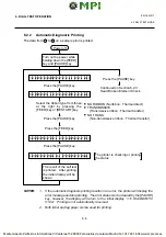
Power off
Press the [RESTART] key.
Press the [RESTART] key.
Press the [FEED] key.
Turn on the power while
holding down the [FEED]
key and [PAUSE] key.
< 1
D I A G N O S T I C
V 1 . O A
>
Press the [RESTART] key.
Press the [FEED] key.
< 2
P A R A M E T E R
S E T
>
Press the [RESTART] key.
Press the [FEED] key.
< 3
T E S T
P R I N T
>
Press the [RESTART] key.
Press the [FEED] key.
< 4
S E N S O R
A D J U S T M E N T
>
Press the [FEED] key.
< 5
R A M
C L E A R
>
e
m
a
N
y
e
K
n
o
i
t
c
n
u
F
y
e
k
]
D
E
E
F
[
e
n
i
f
o
t
r
o
e
d
o
m
r
e
t
e
m
a
r
a
p
e
h
t
d
e
t
c
e
l
e
s
o
t
d
e
s
U
.
s
e
o
d
y
e
k
]
E
S
U
A
P
[
a
s
a
e
d
o
m
m
e
t
s
y
s
e
h
t
t
r
a
t
s
o
t
d
e
s
U
.
)
-
(
n
o
i
t
c
e
r
i
d
e
v
i
t
a
g
e
n
e
h
t
n
i
s
r
e
t
e
m
a
r
a
p
e
h
t
t
s
u
j
d
a
y
e
k
]
T
R
A
T
S
E
R
[
)
+
(
n
o
i
t
c
e
r
i
d
e
v
i
t
i
s
o
p
e
h
t
n
i
s
r
e
t
e
m
a
r
a
p
e
h
t
t
s
u
j
d
a
e
n
i
f
o
t
r
o
e
d
o
m
r
e
t
e
m
a
r
a
p
e
h
t
t
c
e
l
e
s
o
t
d
e
s
U
y
e
k
]
E
S
U
A
P
[
n
a
s
a
d
e
s
U
.
e
d
o
m
r
e
t
e
m
a
r
a
p
e
h
t
t
c
e
l
e
s
o
t
d
n
a
s
e
o
d
y
e
k
]
D
E
E
F
[
a
s
a
e
d
o
m
m
e
t
s
y
s
e
h
t
t
r
a
t
s
o
t
d
e
s
U
.
y
e
k
r
e
t
n
e
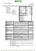
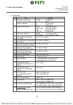
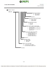
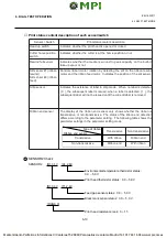
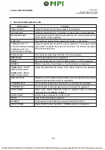
In system mode the [FEED], [RESTART] and [PAUSE] keys function as described below.
■
Key Function Table
(Revision Date: Dec. 10 ‘99)
6.1 OUTLINE OF THE DIAG. TEST OPERATION
6. DIAG. TEST OPERATION
6.1 OUTLINE OF THE DIAG. TEST OPERATION
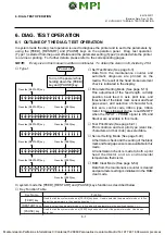
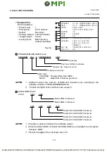
In system mode the diag. test operation is used to diagnose the printer and to set to the parameters by
using the [FEED], [RESTART] and [PAUSE] keys on the operation panel. Diag. test operation
(Type 1) is started from the power off state and the parameter setting (Type 2) is started while the printer
is on-line or printing. For further details, please refer to the corresponding pages.
NOTE:
Every size in this manual is written in millimeter. To obtain the size in inch, divide by 25.4.
■
Type 1
■
Self Test Mode (See page 6-3)
Data from the maintenance counter and
automatic diagnosis are printed on the
media. The result of the head broken element
check is indicated in the display.
■
Parameter Setting Mode (See page 6-13)
Fine adjustment of the feed length, cut/strip
position, back feed, X axis, print tone, and
thresholds of the black mark sensor and feed
gap sensor, and selection of character font,
font zero, control code, ribbon type, ribbon
motor torque, strip wait status, reset ON/OFF
when the INPUT • PRIME signal is ON and
Stacker are available in this mode.
■
Test Print Mode (See page 6-41)
Print condition and test print type (slant line,
characters and bar code) are selectable.
■
Sensor Setting Mode (See page 6-49)
A thermistor check and the setting of the black
mark and feed gap sensors are available in this
mode.
A transmission check is made to both a print
head thermistor and an environmental
temperature thermistor.
■
RAM Clear Mode (See page 6-54)
Data from the maintenance counter is cleared
and parameter setting is initialized in the RAM
clear mode.

