- 130 -
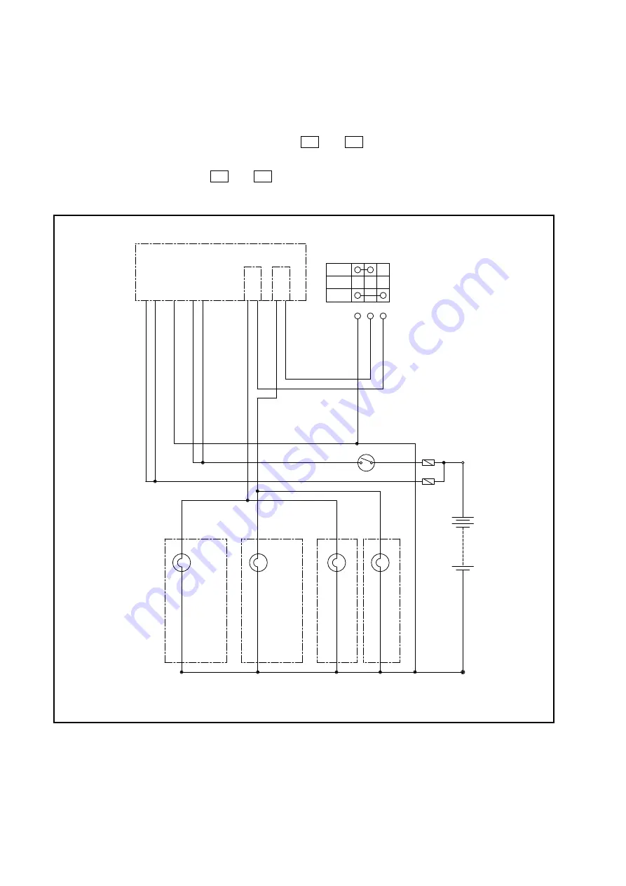
(2) Turn signal switch
The turn signal switch is incorporated into the right lever of the turn signal and light switch
assembly. When the lever is moved forward or backward, the left or right turn signal lights flash
accordingly.
When the lever is moved forward, terminals
TB
and
TL
are connected to each other, causing
the turn signals in the left front and rear combination light assemblies to flash; and when the lever
is moved backward, terminals
TB
and
TR
are connected to each other, and the turn signals in the
right front and rear combination light assemblies flash.
(25W)
(25W)
(25W)
(25W)
N
R
L
TB TR TL
F-9
F-8
F-25
F-24
F-10
F-22
F-13
F-26
(RR)
(RL)
B+
F4
F5
LW 132
G 105
L 131
GR 106
G 105
RG 102
RG 102
B 2
RW12
RW12
R 5
10A
10A
ࡈࡠࡦ࠻
ࠦࡦࡆࡀ࡚ࠪࡦ
ࡦࡊᏀ
ࡈࡠࡦ࠻
ࠦࡦࡆࡀ࡚ࠪࡦ
ࡦࡊฝ
ࡗ
ࠦࡦࡆࡀ࡚ࠪࡦ
ࡦࡊฝ
ࡗ
ࠦࡦࡆࡀ࡚ࠪࡦ
ࡦࡊᏀ
࡙࠾࠶࠻
࠲ࡦࠪࠣ࠽࡞ࠬࠗ࠶࠴
ࡃ࠶࠹
࠲ࡦࠪࠣ࠽࡞ࡦࡊ
࠲ࡦࠪࠣ࠽࡞ࡦࡊ
࠲ࡦࠪࠣ࠽࡞ࡦࡊ
࠲ࡦࠪࠣ࠽࡞ࡦࡊ
Fig. 9.5
Turn Signal Circuit
RELAY UNIT
TURN SIGNAL SWITCH
KEY SWITCH
TURN SIGNAL
LIGHT
TURN SIGNAL
LIGHT
TURN SIGNAL
LIGHT
TURN SIGNAL
LIGHT
BA
TTER
Y
fRONT
COMBINATION
LIGHT (LEfT)
fRONT
COMBINATION
LIGHT (RIGHT)
REAR
COMBINATION
LIGHT (LEfT)
REAR
COMBINATION
LIGHT (RIGHT)
9. ELECTRIC SYSTEM
Summary of Contents for FB-8 Series
Page 2: ......
Page 4: ......
Page 22: ......
Page 26: ......
Page 38: ...NOTE 1 BATTERY 12...
Page 40: ...14 Fig 2 1 Drive Motor Installation DRIVE UNIT DRIVE AXLE DRIVE MOTOR 2 MOTORS...
Page 92: ...NOTE 6 STEERING SYSTEM 66...
Page 106: ...NOTE 6 STEERING SYSTEM 80...
Page 126: ...100 Remove the oil seal from the front cover Fig 7 28 7 HYDRAULIC SYSTEM...
Page 150: ...NOTE 8 LOAD HANDLING SYSTEM 124...
Page 234: ...72 3 TROUBLESHOOTING GUIDE NOTE...
Page 246: ...84 6 ELECTRIC WIRING NOTE...
Page 258: ......
Page 259: ...n m o m Z C F H d o H H M 0 M Z 0 m O m C O R P O R A T I O N T C M...


