background image


  12 / 188 


1. Vehicle information 

Know Before Service 

1. Use good quality tools, or special tools and fixtures designed by our company. The use of inferior tools may cause damage to 

parts, peeling of plating, improper assembly, etc. 

2. The O-rings, paper gaskets, copper gaskets, and component sealing rings used for sealing must be replaced before assembling. 

3. Fasteners with torque requirements need to use a torque wrench to check the torque; if the torque is not required, refer to 

the general torque value recommended by general fasteners. 

4. Clean up before assembly; after assembly, check whether the assembly is correct and in place. 

5. The vehicle should be parked balanced and pay attention to safety during disassembly and assembly. Including but not limited 

to the use of electric tools, hand tools, pneumatic tools, hydraulic tools, handling; prevent contact with skin, eyes, burns, etc. 

6. The replaced oils, liquids, batteries, etc. must be recycled and handed over to qualified institutions for disposal; it is forbidden 

to dump them at will to pollute the environment or water sources. 

7. Swallowing or inhaling coolant, brake fluid, etc. will cause certain harm to the human body. Any exposed skin such as hands 

and face should be cleaned thoroughly after each addition. If swallowed by mistake, immediately contact the poison control 

center or hospital; if inhaled, please immediately go to a ventilated environment. If it accidentally splashes into the eyes, 

immediately rinse the eyes with a large amount of running water and seek medical advice or consultation in time. Keep away 

from children and pets. 

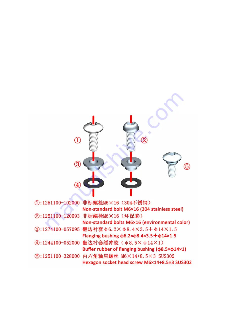
8 M310 and M125 vehicles produced before mid-August 2022 have the structure of M6×16 bolts + flanging b flanging 

bushing buffer rubber, which can be replaced by M6×14 shoulder socket head cap bolts. Similar places in subsequent chapters 

of this manual will not be repeated. 


Only part of the basic requirements for matters needing attention, prevention of accidental injury, etc. can be listed; it is not 

possible to list all situations in detail. Be vigilant during disassembly and assembly to prevent accidents.


Summary of Contents for Zontes ZT125-M 2022

Page 1: ...1 188 ZT125 310T M Maintenance Manual 2022 09 14 ...

Page 2: ...this manual are inconsistent with the official website of Zontes please refer to the official website of Zontes Individual parts of different displacements that differ in shape or size but are disassembled and assembled in the same way will not listed in this manual The M125 steps are similar to the M310 taking the M310 as an example If part of the content of this manual is insufficient please ref...

Page 3: ...s and rubber parts reducing the service life Non woven fabrics should be used for wiping with no residue Ordinary rags may leave cloth scraps or wool etc which may affect the assembly or cause other adverse effects Our company will update this manual as soon as possible after the product changes The following is the meaning of the icons marked in this manual Failure to observe will cause personal ...

Page 4: ...il supply system 22 6 1 M310 Fuel evaporation 22 6 2 M125 Fuel evaporation 23 6 3 M310 Fuel supply 23 6 4 M125 Fuel supply 24 7 Distribution map of cooling system accessories 24 7 1 M310 24 7 2 M125 25 8 Electrical device layout 26 9 Intake and exhaust system 28 9 1 M310 28 9 2 M125 29 Tool 30 Swell nail description 32 2 Maintenance 33 Know Before Service 33 M310 Maintenance schedule 34 M125 Maint...

Page 5: ...deposits 49 3 Remove the throttle valve body assembly to clean up carbon deposits 51 4 Disassemble the three in one sensor 52 5 Throttle valve body troubleshooting process 53 M125 Throttle valve body 53 1 Do not dismantle the throttle body to clean up carbon deposits 53 2 Remove the stepper motor and clean up carbon deposits 53 3 Remove the throttle valve body assembly to clean up carbon deposits ...

Page 6: ...5 2 2 Replace the brake switch 75 3 Lubricate the movable parts of the brake handle 75 3 1 Lubricate the front brake handle 75 3 2 After lubricating the brake handle 75 3 3 Replacing the brake handle 75 4 Adjust the brake handle 75 5 Replace the brake pads 76 5 1 Replace the front brake pads 76 M125 310 76 5 2 Replace the rear brake pads 76 5 3 Abnormal sound of brake pads 77 6 Replace the brake d...

Page 7: ...Headlight height adjustment 95 3 Fuse box 96 4 Troubleshooting 97 4 1 Right hand switch 97 4 2 Right hand handle vice switch 97 4 3Left hand handle auxiliary switch 98 4 4 Horn 98 4 5 Left hand switch 99 4 6 Light 100 4 7 Windshield failure 100 3 EFI system 101 Know Before Service 101 Error code 102 1 M310 Read the fault code through the meter 102 2 Read the fault code through the diagnostic tool ...

Page 8: ...w Before Service 121 Troubleshooting 121 1 Starting relay 121 2 Starter motor 122 3 The starter motor runs slowly 122 4 The starter motor is working normally but the engine cannot be started 122 Ignition system layout 122 Starting system electrical schematic diagram 123 Starter motor 123 1 Remove the starter motor 123 2 Disassemble the starter motor 124 Examination 125 Starter motor front cover 12...

Page 9: ... water pump cover assembly M310 139 8 Braking system 140 Know Before Service 140 Trouble shooting 141 Soft feeling from brake lever 141 Hard feeling from brake lever 141 Disassemble the disc brake main pump and calipers 141 Disassemble the front disc brake main pump 141 Disassemble the rear disc brake main pump 142 Disassemble the front disc brake caliper 142 Disassemble the rear disc brake calipe...

Page 10: ... wheel rims and tires 163 3 1 The service life of the front wheel rim and tire 163 3 2 How to replace the front wheel rim and tire 164 3 3 Dynamic balance 164 Replacement of the front shock absorber 164 1 Disassemble the front wheel and front fender assembly 164 2 Remove the left and right front shock absorbers 164 3 Reinstall the shock absorber front fender front wheel and other components 165 Re...

Page 11: ... Disassembly of the surrounding bottom 181 Removal of the cooling fan air guide plate 181 Disassembly of the cushion 181 Disassembly of the storage box 182 Disassembly of the rear hand rest 182 Disassembly of the left and right tail cover 182 Disassembly of tail light 183 Disassembly of rear fender 183 Disassembly of the left right fuel tank cover 185 Disassembly the middle cover of the fuel tank ...

Page 12: ...er to qualified institutions for disposal it is forbidden to dump them at will to pollute the environment or water sources 7 Swallowing or inhaling coolant brake fluid etc will cause certain harm to the human body Any exposed skin such as hands and face should be cleaned thoroughly after each addition If swallowed by mistake immediately contact the poison control center or hospital if inhaled plea...

Page 13: ...ve the muffler The nameplate is above the radiator PKE OBD interface and water tank filling port position are pasted on the right storage box cover The engine identification code is engraved on the left crankcase The storage box warning label is pasted on the front of the storage box Remarks Different rows of nameplate muffler code and warning paste content is different The figure below is illustr...

Page 14: ...tat fully open temperature 95 203F Thermostat opening stroke 3 5mm 0 13 in Coolant type Ethylene glycol distilled water Front wheel steering system Item Standard Limit Tread depth 1 6mm 0 063 in Normal temperature standard tire pressure 260kPa 2 7 kgf cm2 37 7 PSI Front wheel rim runout Radial 1 5mm 0 006 in Axial 1 5mm 0 006 in Rear wheel suspension system Item Standard Limit Tread depth 1 6mm 0 ...

Page 15: ...specification 120 70 14 CM577 61P Front rim specification MT 2 5 14 Rear rim specification MT 3 5 14 Brake fluid DOT4 0 23L 0 06 US gal 0 05 lmp gal Oil consumption Replace fine filter 0 95L 0 25 US gal 0 21 lmp gal Without replacing the fine filter 0 9L 0 24 US gal 0 2 lmp gal Gearbox oil consumption 0 16L 0 04 US gal 0 04 lmp gal Engine Idle speed r min 1500 100 Fuel oil 95 and above Spark plug ...

Page 16: ...rake fluid DOT4 Brake pad use limit Trough bottom Brake disc thickness 4 0mm 0 16 in 4 0mm 0 16 in Battery charging system Item Standard Battery Type 6 FM 7L Capacity 7Ah Battery self discharge current 1 1mA average Voltage Full 13 1 13 3V Charging voltage required for unloaded bike 12 8V Charging voltage required for loading 12V Constant voltage charging mode Constant voltage range 14 4 14 8V Ini...

Page 17: ...4 0 KΩ Tightening torque Bolt tightening torque of general tightening part Intensity level Grade 4 8 6 8 mark 4 on the head of the bolt Grade 8 8 mark 7 or 8 8 on the head of the bolt Bolt diameter Tightening torque range Standar d value Breaking torque Tightening torque range Standard value Breaking torque M4 1 2 1 4 1 5 3 2 5 M5 2 4 2 9 4 5 3 6 4 5 8 M6 4 7 4 9 10 8 12 10 14 5 M8 10 16 12 2 20 1...

Page 18: ...osition light 5 Right daytime running light 6 Headlight 7 Right front turn signal 8 Right hand handle auxiliary switch 9 Right hand handle switch 10 Rear tail light system Moving lamp 11 Rear right turn signal 12 Rear reflector 13 License plate lamp 14 Left rear turn signal 15 Left handle switch 16 Left handle assistant switch 2 Throttle cable 1 Oil return line 2 Fuel line ...

Page 19: ...e main pump 4 Calipers brake hoses and wheel speed sensors 1 brake disc front 2 front whell ABS induction ring gear 3 wheel speed sensor front wheel 4 front disc brake caliper 5 FC HU brake hose 6 rear whell ABS induction ring gear 7 brake disc rear 8 rear disc brake caliper 9 wheel speed sensor rear wheel 10 RC HU brake hose ...

Page 20: ...ront wheel 2 FC HU brake hose 3 RC HU brake hose 4 wheel speed sensor rear wheel 5 rear brake lever 6 rear brake switch 7 RMC HU brake hose 8 rear disc brake main pump 9 FMC HU brake hose 10 front brake switch 11 front disc brake main pump 12 front brake handle 13 hydraulic control unit ...

Page 21: ... hose 3 RC HU brake hose 4 wheel speed sensor rear wheel 5 rear brake lever 6 rear brake switch 7 RMC HU brake hose 8 rear disc brake main pump 9 FMC HU brake hose 10 front brake switch 11 front disc brake main pump 12 front brake handle 13 hydraulic control unit ...

Page 22: ... vent pipe 6 a solenoid valve intake pipe 10 a solenoid valve outlet pipe 11 and a vent leakage pipe 13 The carbon canister components are sold as a complete set and are sold separately without being disassembled If the vent tube is damaged you can purchase a reliable and weather resistant hose with the same or similar inner and outer diameters A small amount of gasoline that enters the canister a...

Page 23: ... 11 solenoid valve outlet pipe 12 throttle valve body assembly Fuel evaporation Oil and gas oil and gas separator inside the oil tank adsorption vent pipe solenoid valve intake pipe solenoid valve outlet pipe throttle valve body assembly intake manifold cylinder 6 3 M310 Fuel supply Fuel supply system Air Carbon canister Adsorption vent pipe Oil separator inside the oil tank Fuel Fuel pump filter ...

Page 24: ...lter screen Fuel pump High pressure fuel pipe Fuel injector Cylinder 7 Distribution map of cooling system accessories 7 1 M310 1 Main water tank 2 Water tank filling port 3 Secondary water tank 4 Aluminum water inlet pipe 5 Aluminum water outlet pipe 6 Small water tank 7 Water and oil shared sensor 8 Thermostat 9 Water pump cover assembly ...

Page 25: ...Secondary water tank link pipe 3 Engine inlet pipe 4 Thermostat outlet pipe 5 Thermostat 6 Water tank inlet pipe 7 Water and oil shared sensor 8 Water tank outlet pipe 9 Water tank filling port 10 Radiator assembly 11 Water pump cover assembly ...

Page 26: ...ucet lock 5 PKE 6 main cable 7 ignition coil 8 side bracket flameout switch 9 engine controller ECU 10 buzzer 11 cushion lock 12 Dump switch 13 Windshield motor controller 14 USB charging cable 15 Front storage box lock 16 Electronic fuel tank lock 17 Canister solenoid valve ...

Page 27: ...3 PKE 4 faucet lock 5 front storage box lock 6 speaker 7 USB charging cable 8 dump switch 1 Cushion Lock 2 Rectifier 3 Buzzer 4 Engine Controller ECU 5 Battery 6 Fuse Box 1 7 Electronic Fuel Tank Lock 8 Fuse Box 2 9 Fuse Box 3 10 Ignition Coil 11 Side Bracket flameout switch ...

Page 28: ...r filter intake pipe Air filter element Air filter outlet pipe Throttle valve assembly body Intake manifold Cylinder Muffler Cylinder head exhaust gas control system red arrow indicates Exhaust gas cylinder head cover oil and gas separator cylinder head exhaust pipe air filter air filter outlet pipe throttle valve body intake manifold cylinder muffler Gearbox exhaust gas control system indicated b...

Page 29: ... Air filter element Air filter outlet pipe Throttle valve assembly body Intake manifold Cylinder Muffler Cylinder head exhaust gas control system red arrow indicates Exhaust gas cylinder head cover cylinder head exhaust pipe air filter air filter outlet pipe throttle valve body intake manifold cylinder muffler Gearbox exhaust gas control system indicated by the blue arrow Exhaust gas gearbox exhau...

Page 30: ... piece tool set Torque wrench On board tools Claw hammer Pull code Rubber hammer Dynamic Balancing Machine Tire raking machine Oil pan Measuring cup Funnel Taps dies Micrometer Depth gauge Vernier caliper Feeler gauge ...

Page 31: ...g diagnostic Speedometer 16PIN 17 Inner hexagon Hoop clamp Internal Circlip Pliers External circlip pliers Clamp multimeter Multimeter Dust blow gun Some of the above pictures are from the Internet and the copyright belongs to the author of the original picture Do not use it for other purposes ...

Page 32: ...the outer ring with two fingers and push the center cylinder up to the initial position Pinch the center cylinder with two fingers to install the swell nails to the installation position The outer ring is attached to the connected parts if not attached Check whether it is misaligned Press the center cylinder with your fingers or other tools and you can hear a sound or the top of the center cylinde...

Page 33: ...ical advice or consultation in time Keep away from children and pets 8 If you need to clean or wash the body parts of the vehicle you should use neutral car wash fluid or tap water diesel kerosene etc Acidic or alkaline car wash fluid will cause irreversible corrosion of the surface paint electroplating surface and anodized surface of the parts gasoline will cause premature aging or hardening of s...

Page 34: ... mile Braking System I I Brake hose I Every 4 years Brake fluid I Every 2 years Tire I Steering mechanism bolts and nuts T T First adjust nut 15 2 1 5 0 2 the second adjust nut align the first nut Steering bearing in Steering mechanism Every5000km 3107mile inspection or clean or lubricate Front shock absorber I Rear shock absorber I Bolts and nuts for body and engine installation T T M12 65 5 6 6 ...

Page 35: ...ng bearing in Steering mechanism Every 4000km 2485mile inspection or clean or lubricate Front shock absorber I Rear shock absorber I Bolts and nuts for body and engine installation T T M12 65 5 6 6 0 5 M16 80 5 8 2 0 5 Coolant I I 4 years or 40 000 kilometers 24855 mile Gearbox oil R R Valve clearance cold inspection In 0 08 0 12mm 0 003 0 005 in Row 0 12 0 16mm 0 005 0 006 in I This service is pr...

Page 36: ... should be increased Steering system braking system electronic fuel injection system shock absorber and wheels are all key components and it is recommended to be carried out by a qualified maintenance organization M310 Air filter filter element air inlet filter element Step 1 Support the vehicle firmly Prop up the vehicle with the main bracket and put down the side brackets as shown in the figure ...

Page 37: ...ion shown 5 Remove the air filter housing a Use a Phillips screwdriver to remove the 9 screws that fix the housing of the air filter b Remove the air filter housing 6 Replace Air filter element a Use a Phillips screwdriver to remove the 6 screws that fix the filter element that comes with the air filter b Remove the old air filter element Blow the dust inside the air inlet pipe with a dust blower ...

Page 38: ...l the other 4 M6 14 bolts Replace the decorative buckle The vehicle must be parked on a flat and stable ground or a lifting platform The operation can only be performed after the engine has cooled down completely The air filter element and the engine air inlet element should be replaced every 10000km 621 mile The air filter element and the engine air inlet element should be cleaned regularly in ac...

Page 39: ...exagon to remove the M6 14 bolt as shown in the figure The bolt here cannot be removed temporarily just loosen it completely b Use 4 inner hexagon to press down the center cylindrical pins of the 2 swell nails and then remove the swell nails and the engine rear decorative cover c Use 4 inner hexagon to remove the 4 pcs Hexagon socket head screw M6 14 bolts as shown in the figure d Remove the front...

Page 40: ...Wipe clean the surface of the waste oil pipe and visually check for liquid If so use pliers to remove the waste oil pipe clamp clean the waste oil pipe and then reinstall it Pay attention to increase the frequency of inspection appropriately when the air humidity is high 7 Reinstall a Refer to the steps of removing the filter housing to install the housing back b Replace the air inlet baffle and t...

Page 41: ...n to blow air from the clean side of the filter element to blow away the dust on the surface of the filter element Do not let water enter the air filter when washing the vehicle Bolts and nuts of muffler 1 Check for air leaks at the engine exhaust The modelsⅠ The modelsⅡ The models Ⅲ a If there is a slight air leak first try to tighten the exhaust port nut with 6 inner hexagon if the problem is no...

Page 42: ...the 4 inner hexagon to remove the M6 14 bolts b Pull out in sequence in the direction of the arrow from the rear wheel to the front wheel Note that there are 5 staples at the red circle and a circle of buckles around It takes a lot of force to pull out c Use your fingers or a plastic crowbar to insert the arrow indication point first pry the arrow indication point open the gap and then pull up d R...

Page 43: ... cracked or damaged whether the center electrode is abraded fouled corroded excessively carbonized or discolored the color of the ceramic insulator around the middle electrode of the spark plug should be light brown If so replace the spark plug with a new one b Clean the electrode with a special spark plug cleaner Use a hard iron wire or steel needle to remove the attached carbon deposits c Use a ...

Page 44: ...es at the red circle and a circle of buckles around It takes a lot of force to pull out c Use your fingers or a plastic crowbar to insert the arrow indication point first pry the arrow indication point open the gap and then pull up d Respectively use 4 inner hexagon to remove the 2 M6 12 bolts at the front pedal e Use 4 inner hexagon to remove the 3 M6 14 bolts that surround the right side f Use y...

Page 45: ... or steel needle to remove the attached carbon deposits c Use a feeler gauge to inspect the gap between the center electrode and the side electrode d If necessary the gap can be adjusted by bending the side electrodes paying attention to the strength during adjustment e Clean the surface of the spark plug gasket and the joint surface and wipe off the dirt on the thread f First screw it back to the...

Page 46: ... dipstick and O ring to accelerate the oil flow d After placing an oil pan under the oil drain bolt use a 14 sleeve to remove the oil drain bolt and the combined seal gasket e Wipe clean the joint surface with a non woven fabric Inspect the oil drain bolt whether the joint surface is scratched if there is any replace it with a new one if not wipe it clean f Replace the new combination gasket and u...

Page 47: ...up with 0 2L of oil or gearbox special oil 0 21US qt 0 18 lmp qt 0 05 US gal 0 04 lmp gal g Check whether the O ring is damaged or aging wipe it clean if not and replace it if there is any h Wipe clean the nut and the fuel filler port with a non woven cloth first put the O ring into the nut and then turn it clockwise by hand and install it back to the fuel filler port of the gear box 5 Confirm the...

Page 48: ...er c Remove the fine filter cover and O ring 3a Remove the spring the fine filter oil filter element 3b and the gasket 3c in sequence d Replace the new fine filter oil filter element and gasket The fine filter assembly already contains O ring 3a fine filter oil filter element 3b and gasket 3c Replace in order e Remove the O ring on the fine filter cover and replace it with a new O ring First put t...

Page 49: ...itions are leaking and if there is any leakage it needs to be checked b After the engine has been idling for 5 minutes and then turned off for 3 minutes check whether the oil level meets the standard If it does not meet the standard draw it out or add it to the standard M310 Throttle valve body Caution The three in one sensor and stepper motor cannot be immersed in any liquid It is forbidden to ad...

Page 50: ...h 7 2022 follow this step and for vehicles produced after that skip directly to step h e Pull up the 3 fuse boxes and pull out the cables When re installing you need to insert the fuse box back to the corresponding position and arrange all the cables otherwise it will be difficult to fit the battery cover in place f Pull out the two relay wires There are a total of 8 relays the model is KH 1A4T g ...

Page 51: ...rd obliquely paying attention to the cables in the battery compartment Pull up to see the left side of the glove box atmosphere lamp thread unplug the thread and remove the glove box assembly l Unplug the plug of the stepping motor m Use a short Phillips screwdriver to remove the 2 GB9074 4 M4 12 bolts and the anti off card that come with the throttle valve body assembly and then remove the steppi...

Page 52: ...et respectively It is forbidden to directly soak the throttle valve body assembly and intake manifold assembly with any liquid h After cleaning the heat insulation pad replace 2 new O rings and assemble them in place Wipe clean the contact surface of the intake manifold and the heat insulation pad and the end surface of the heat insulation pad and the engine Reversely reset all materials in the or...

Page 53: ... are disassembled do not miss the sealing ring and make sure that the sealing ring is assembled in place without cutting edges Do not use carburetor cleaner or compressed air to clean the throttle valve body The EFI system needs to be reset after reinstalling the battery The specific method is as follows a Unlock the vehicle and support the main bracket b Pinch the brake and start the vehicle c Pu...

Page 54: ...ewdriver to remove the 2 GB9074 4 M4 12bolts and the anti off card that come with the throttle valve body assembly and then remove the stepping motor g Use throttle cleaner to clean the carbon deposits on the head of the stepper motor Spray a small amount of cleaning agent into the valve body hole It is forbidden to soak the stepper motor with any liquid o Install the stepper motor back to the val...

Page 55: ...without ignition turn the throttle handle from the initial position to fully open and check whether the throttle position signal changes from 0 to 100 e Check whether the external intake pressure sensor is damaged Loosen the connector and check whether the pin is skewed or broken The vehicle is connected to the diagnostic instrument without ignition Check the engine parameters to see whether the p...

Page 56: ...le or the rubber sleeve of the right handle d After starting the engine turn the steering handle left and right to ensure that the idling speed does not change during the steering process and then turn off the engine e Rotate the right hand to check whether the rubber sleeve inspection cable gap is within 2 4mm 0 1 0 2 in 2 Adjust the throttle cable clearance a Fix the adjusting screw with a 8 ope...

Page 57: ...ight should not light up The status of the spark plug has been checked The air filter element and the air inlet element have been inspected or replaced Check the throttle clearance The limit screw on the valve body is not allowed to be adjusted privately Check idle speed Check the idling speed of the engine when the engine is warm M310 the idle speed range of the engine should be 1500 1700 rpm M12...

Page 58: ... intake pipe 11 solenoid valve outlet pipe 12 throttle valve body assembly Remarks The carbon canister assembly includes carbon canister 8 adsorption vent pipe 6 solenoid valve inlet pipe 10 and solenoid valve outlet pipe 11 The carbon canister components are sold as a complete set and are sold separately without being disassembled If the vent tube is damaged you can purchase a reliable and weathe...

Page 59: ... running water and seek medical advice or consultation in time Keep away from children and pets The engine coolant must be a model suitable for aluminum radiators based on ethylene glycol Use a coolant that is suitable for aluminum radiators which is a mixture of coolant concentrate and distilled water in a certain proportion If you need to add water you can only add distilled water Other water qu...

Page 60: ...ntainer is required to receive the coolant overflowing from the exhaust bolt Do not allow the coolant to drip directly onto the surface of the part d Put on waterproof gloves and add coolant to the water inlet of the Radiator with the help of an extended funnel Until the position of the vent bolt of the thermostat is stably overflowed with coolant the coolant level can be seen at the water filling...

Page 61: ...c to remove dirt sand insects and other dirt on the surface of the radiator When using compressed air be careful not to get too close to the fins It is forbidden to flush the radiator directly with a high pressure water gun to prevent the fins from deforming and blocking the air duct b Pull the deformed fins straight with a flat engraving knife or a small flat blade screwdriver If the deformed fin...

Page 62: ...r 6 Water and oil shared sensor 7 thermostat 8 water pump assembly 1 Main water tank inlet pipe 2 Leakage pipe 3 Small radiator outlet pipe 4 Water inlet pipe 5 Secondary water tank connection pipe 6 Main water tank outlet pipe 7 Engine inlet pipe 8 Small radiator inlet pipe 9 Small circulation outlet pipe 10 Water pump cover inlet pipe 11 Cylinder inlet pipe ...

Page 63: ...condary water tank link pipe 3 Engine inlet pipe 4 Thermostat outlet pipe 5 Thermostat 6 Water tank inlet pipe 7 Water and oil shared sensor 8 Water tank outlet pipe 9 Water tank filling port 10 Radiator assembly 11 Water pump cover assembly ...

Page 64: ...e cushion and storage box components and remove them as shown in the figure below b Remove a total of 4 pcs swell nails indicated by the arrow For instructions on disassembly and assembly of swell nails please refer to the pre service instructions in this chapter Use 4 inner hexagon to remove the M6 14 bolts c Press the blue part inward at the junction of green and blue as shown in the figure pull...

Page 65: ...il pipe of the original car to the pressure gauge and find another high pressure oil pipe to connect the pressure gauge and the fuel injector Start the vehicle let the engine run at idle speed and measure the fuel pressure M125 310 the standard pressure is 300 10kPa 3 06 0 1Kgf cm2 43 5 1 45 psi Check valve performance hold the pressure for 1 minute the pressure should be 240kPa 2 45Kgf cm2 34 8 p...

Page 66: ...lition site The fuel pump is a precision component that needs to be assembled in a dust free workshop and requires strict testing so it is forbidden to disassemble it by yourself The EFI system needs to be reset after reinstalling the battery For specific operations see the precautions in the driver s manual or the throttle valve body chapter of this manual ...

Page 67: ...heel clutch cover 1 6 Driving wheel sliding plate 1 15 Driven wheel clutch shoe 1 7 Pulizhu 8 16 Sliding plate of driven wheel 1 8 Boot block 1 17 Driven wheel fixed disk 1 9 Ramp board 4 2 Maintenance Caution Special tools are required to disassemble the driving wheel and driven wheel components It is recommended to regularly check and replace it by a designated dealer or repair shop Belts should...

Page 68: ...cover and the left crankcase cover gasket The left crankcase cover gasket 4 must be replaced when reinstalling and the hollow positioning pin 3 must not be omitted 2 2 Disassemble the continuously variable transmission components a Align the cylindrical bayonet pins of the dedicated master and driven wheel positioning fixtures respectively with the two positioning holes inserted into the outer bla...

Page 69: ...y variable clutch sub assembly 2 3 Inspection Caution Every 3 years or driving 20000 kilometers 12427 mile the continuously variable clutch sub assembly needs to be inspected maintained or repaired a Inspection items and use limits of the driving wheel Use a knife edge ruler to align the tapered working surface of the driving wheel drive disk and sliding disk in parallel and then use a feeler gaug...

Page 70: ...xed shaft of the driven wheel are worn or damaged If they are worn loose and loose frames they need to be replaced Note that the bearings don t need to be geased to prevent the grease from slipping on the belt 2 4 Assembly Caution Before assembling it is necessary to conduct a comprehensive inspection of all the parts of the disassembled continuously variable clutch sub assembly and replace the pa...

Page 71: ...uickly extend your finger near the side of the V shaped drive belt to slide the V shaped drive belt into the belt groove between the moving plate of the driven wheel and the fixed plate Finally clamp the middle of the belt with an elastic clip to prevent the belt from loosening by itself Caution This step requires greater hand strength and certain operating experience to complete Insufficient hand...

Page 72: ...troubleshooting 3 1 The engine can be started but the rear wheel does not rotate a The V shaped transmission belt is severely worn or broken b The clutch shoe is worn or damaged c The large spring of the driven wheel is damaged d The spline of the clutch cover and the drive shaft is damaged 3 2 Engine stall or lack of power a The V belt is slipping b The large spring of the driven wheel is damaged...

Page 73: ...hoses disc brake calipers disc brake main pumps and hydraulic control units must be reviewed by our company before they can be purchased Domestic customers can fill in the frame code and engine on the official website before purchasing Foreign customers need to contact the corresponding salesperson and fill in the corresponding form before purchasing The specific process can be found by the salesp...

Page 74: ...eep scratches grooves etc Replace it if necessary Feel with your hands whether there is a noticeable sound of grinding the brake disc when turning the front wheel Observe from the front whether the brake disc swings when turning the front wheel if there is any swing please remove it according to the steps of dismantling the brake disc and place it on a standard platform use a dial indicator to mea...

Page 75: ...out distinguishing the positive and negative poles b Use a Phillips screwdriver to remove the bolt to remove the rear brake switch c Replace with a new switch pay attention to align the switch boss and the limit hole of the brake main pump The replacement procedure of the front brake switch is the same as that of the rear brake switch The throttle cable needs to be removed to facilitate the remova...

Page 76: ...end in the direction of the arrow with the help of a tool If the resistance is high you can refer to the method of adding brake fluid to the front brake main pump to remove the upper cover and then push If the spring on the caliper falls off it needs to be reinstalled in the direction shown in the figure d Take out the new brake pad and install it back You need to hold the bottom of the brake pad ...

Page 77: ...as follows a The brake pad is worn to the limit If it is a new brake pad check whether there is any foreign matter caught between the brake disc and the brake pad It can return to normal after replacing new brake pads or cleaning foreign objects b Use non original brake pads with too high hardness and replace them with original ones c The brake disc bolts are loose and the tightening bolts can be ...

Page 78: ...the M6 14 bolt on the right middle of the rear inner mudguard use 4 hex socket to remove the front M6 12 bolt and the rear M6 16 bolt Remove the two M6 12 bolts at the bottom of the rear rocker arm and remove the wheel speed sensor Pull out the staples on the position indicated by the arrow and remove the decorative cover of the engine right cover d In the gap between the left air filter and the r...

Page 79: ... brake fluid and it is forbidden to mix it with other brake fluids Wear protective gloves protective clothing protective goggles protective masks Brake fluid must be used in time after opening seal and moisture proof measures must be taken when storing it is recommended not to exceed 1 month Inferior or damp brake fluid will cause adverse effects on the brake system and may cause brake failure whe...

Page 80: ...end of the hose into the oil pot d Remove the upper cover of the front brake main pump referring to the previous step of adding brake fluid e Rotate the 8 torx wrench with the right hand counterclockwise to loosen the air nozzle and with the left hand slowly and uniformly squeeze the front brake handle to the end and keep it still Lock the vent nozzle clockwise and slowly loosen the handle Pay clo...

Page 81: ...e sidewall is bumped punctured scratched or if the tread is damaged and the hole is large it should be replaced directly Rebalance should be done after Tyre repair Check the tire pressure regularly M310 the standard is 260kPa 2 7 kgf cm2 37 7 PSI under normal temperature conditions M125 front tire is 220kPa 2 2 kgf cm2 32 PSI rear tire is 270kPa 2 75 kgf cm2 39 PSI The maximum tire pressure in the...

Page 82: ...intenance table Park the vehicle on a flat and stable ground or a lifting platform and put down the main support Too small steering mechanism clearance will cause inflexible steering and accelerate bearing wear When it is too large it will cause driving jitter and abnormal noise when braking 1 Check the steering mechanism a Support the front wheel with a suitable tool so that the front tire is hun...

Page 83: ...0 07 US oz 7 7 0 07 lmp oz 13 4 0 1 cu in After traveling on dusty or muddy roads you should clean up the foreign matter on the front fork tube exposed chrome plated cylinder in time to avoid scratching the dust seal or oil seal and causing leakage wipe it clean with a soft cloth Do not use a high pressure water gun to directly flush against the dust seal at close range The vehicle should be parke...

Page 84: ...slowly and slightly straighten the pressure and small stroke several times and measure while straightening The radial run out after correction should be less than 0 05mm 0 002 in If the original bending deformation part is out of round after correction it should be replaced If the deformation is too large the shock absorption should be replaced 5 Troubleshooting a There is obvious impact noise whe...

Page 85: ...rear shock absorption 2 2 1 M310 a Refer to the previous steps to replace the air inlet filter element and remove the left cover Disassemble it as shown in the figure below b Use an 8 sleeve to remove the bolts 1 at the position shown in the figure c Use needle nose pliers to clamp the exhaust pipe clamp on the inner side of the air filter and move it upward about 20mm 0 8 in Pull the exhaust pipe...

Page 86: ...e on the outside and remove the nut Be careful not to remove the bolt first Remove the nut by the same operation on the other side One person supports the rear wheel assembly and one person removes the bolts on both sides lower the rear wheel assembly to the ground Nut torque standard 30N m 3 1 kgf m 22 lbf ft f Grasp the rear right shock absorber and use a 12 sleeve to remove the bolt and remove ...

Page 87: ...e fixed engine as shown in the figure are loose The nut on the right front part a in the figure needs to be pulled out or pulled out of the high pressure oil pipe and cable connector to facilitate tightening with tools c Use 4 inner hexagon to remove M6 14 bolt Grasp the rear left pedal assembly and use a 12 sleeve to remove the 2 M8 35 bolts and then remove the pedal assembly Remove the rear righ...

Page 88: ...gs b Feeler gauge c Thread fastening glue and sealing silica gel 2 Operation steps a Use an 8 T shaped socket wrench or a wind batch to remove the 6 M6 30 hexagonal flange bolts of the cylinder head cover and then remove the cylinder head cover assembly b Use 5 and 10 Allen wrenches to remove M14 1 5 screw plugs and M30 1 5 aluminum screw plugs and remove the O ring c Insert the 14 T shaped socket...

Page 89: ...e You need to increase the clearance of 0 04 0 08mm 0 002 0 003 in The thickness specification of the original adjusting gasket on the engine is 2 36mm 0 093in you need to replace the adjusting shim with 2 28 2 32mm 0 09 0 091 in According to this method determine the specifications of the adjusting shim for the four valves to be replaced and place them according to the records made before to prev...

Page 90: ...oint surface of the cylinder head and the seal ring of the cylinder head with a clean rag and reapply a proper amount of sealing silicone on the corners of the joint surface of the cylinder head Then install the cylinder head cover assembly corresponding to the shape of the joint surface Use 8 T shaped socket wrench or wind batch to lock the cylinder head cover 6 M6 30 hexagon flange bolts the tor...

Page 91: ...91 188 l So far the adjustment operation of the valve clearance is completed ...

Page 92: ...r brake handle After starting the vehicle put down the side brackets and the flame should be automatically turned off otherwise it is necessary to troubleshoot the flameout switch or brake switch failure d Check whether the side bracket mounting plate is deformed or cracked 2 Lubrication a Put away the side bracket so that the spring is in the shortest position for easy disassembly b The thick ste...

Page 93: ... main support shaft 3 from right to left Pay attention to the protection measures at the spring of the main support to prevent the spring of the main support from suddenly loosening and flying out and causing personal injury It can be covered by a hard object or the spring can be tied up with a rope or thin iron wire b Remove the spring from the main support c Apply a proper amount of grease to th...

Page 94: ...to test whether it is normal SET key Short press SET to enter the main menu confirm selection Long press to return to the main interface Operate this button when driving a vehicle is prohibited MOD key Select the next item Operate this button when driving a vehicle is prohibited Windshield switch Press the windshield glass to complete from retracting to opening or from opening to retracting Steeri...

Page 95: ... charger is the TEST button which function is same as the unlock button on the auxiliary switch 2 Headlight height adjustment Caution The height of the headlights is too high or too low which will affect safe driving The light height should be adjusted reasonably according to the presence or absence of the occupant and the weight change of the driver It is strictly forbidden to adjust the light he...

Page 96: ...box After opening the fuse box cover check whether the fuse is normal No Name Function Specification Main insurance Protect all circuits 25A ECM Protect ECM ECM relay oil pump relay and other electrical devices 15A Regular power supply Protect fans meters and anti theft device connectors 15A Hydraulic control unit motor Protect ABS hydraulic control unit motor 25A Reserve 25A Reserve 15A Hydraulic...

Page 97: ...t is judged as a switch failure Otherwise check for cable or headlight failures c The E S mode cannot be switched by pressing the ECO button Disconnect the switch and short the ECO button switch line If it is lit it is judged as a switch failure If it is not lit check the meter and cable failure 4 2 Right hand handle vice switch a FUEL Button failure Short press FUEL no response Whether the batter...

Page 98: ...ion There should be more than 5 seconds interval when adjusting or checking the horn Continuous sounding may cause ablation of the internal coil of the horn The horn is a riveted structure which is difficult to restore after disassembly It is prohibited to adjust the bracket nut a If the horn switch does not respond please refer to the troubleshooting process of the left hand switch on the next pa...

Page 99: ... see if the turn signal is on Light failure Y Check whether the meter is on Y Press the double flash button is it on There is also a problem with the double flash button The chances are small The near high beam does not light up Disassemble the handle switch and short circuit the light switch line Is it on N Y N Troubleshoot cable faults Check whether the secondary insurance powder is burned Doubl...

Page 100: ...process of lamp troubleshooting After power on turn on the left right hand switch and the lamp does not light up Check whether the lighting terminal is plugged in N Reconnect the terminals Y Unplug the plug connect the lamp and the battery with a wire N Damaged lights Troubleshoot switch or cable failure Y Check if the insurance is blown N Replacement insurance Y 4 7 Windshield failure When the wi...

Page 101: ... the flameout switch and lock the car e After waiting for 5 seconds unlock the vehicle again to complete the reset of the EFI system 7 Pay attention to the following when checking or troubleshooting EFI system failures a After power on the parts connected to the 12V power supply should not be removed at will to avoid the self inductance of the coil in the electrical appliance and cause the instant...

Page 102: ...ontinuous flashing 10 times intermittent 1 second continuous flashing 2 times intermittent 1 second continuous flashing 10 times intermittent 1 second Flashes once in a row c If there is more than one fault the next fault code will flash after the fault light is off for 4 seconds Therefore after the fault light is off during the flashing process waiting for more than 5 seconds and still no longer ...

Page 103: ...ntrol circuit is shorted to the power supply P0444 Canister solenoid valve open P0322 No speed sensor pulse signal open circuit or short circuit P0459 Canister solenoid valve is shorted to the power supply P0480 Fan control circuit is open P0458 Canister solenoid valve is shorted to ground P0691 Fan control circuit is shorted to ground P2300 1 cylinder ignition coil is shorted to ground P0692 The ...

Page 104: ... Ignition coils M310 Throttle valve body M310 Water and oil shared sensor Oxygen Sensor M310 MSE6 0 ECU M310 Crankshaft position sensor M310 13 14 15 16 17 18 Oxygen Sensor M125 Fuel injector M125 Ignition coils M125 External intake pressure sensor M125 Throttle Body Assembly M125 Crankshaft position sensor M125 19 20 Air filter intake air temperature sensor M125 MSE8 0 ECU M125 ...

Page 105: ... of the vehicle please be sure to go to a regular gas station to refuel It is forbidden to run the fuel pump in dry state or in water otherwise its service life will be shortened and it will be directly damaged in severe cases The positive and negative wires of the fuel pump cannot be connected in reverse It is forbidden to disassemble the fuel inlet filter which may cause foreign matter to enter ...

Page 106: ... function is the same Cable end wire color Wire no Relay 1 2 3 5 light Red Blue w hite Black and white White Start assist green Green red Black white Red green Oil pump White black Red bl ack White black Green y ellow Main relay Red White black Black white Orange black Wire no Relay 1 2 3 5 Front motor green Light green black White cooling fan green Green white black Green blue 6 Fuel injector Whe...

Page 107: ...brackets use the main bracket to park the vehicle firmly and unlock the vehicle turn the flameout switch to hold the brake handle and place the spark plug close to the engine cylinder head cover or box should be far away from the spark plug mounting screw hole about 6mm 0 24 in press the start button If a blue spark is found on the spark plug electrode the ignition system is normal otherwise it sh...

Page 108: ...ce of the two terminals T and G can be measured to determine whether it is abnormal The resistance value at 25 C 77F is 1940 2040Ω M125 sensor For the disassembly assembly and inspection of the M125 throttle valve body position sensor and the external intake pressure sensor please refer to the previous section on the throttle valve body Air filter intake air temperature sensor Remove the temperatu...

Page 109: ...olor of the top part of the head which is normally light gray If it is white it means that the silicon poisoning has been damaged and needs to be replaced if it is black it means that there is carbon deposits that can be cleaned up and continue to use if it is brown it means that the silicon poisoning needs to be replaced 10 2 Replace M310 First pull out the plug use needle nose pliers to remove t...

Page 110: ... rear storage box rear armrest and rear right rear skirt Pull out the ECU plug after pressing the buckle indicated by the arrow Remove 2 M6 12 bolts with 4 hexagon socket to remove the ECU 12 Crankshaft position sensor When the engine starts without dust or is difficult to start poor acceleration and unstable idling when the engine is stalled intermittently it is necessary to check whether the cra...

Page 111: ...en the start button is pressed the starter motor can drive the engine to run normally When there are signs of a car but cannot start you can refer to the following diagnosis process to troubleshoot the cause of the fault Check the diagnostic code with a diagnostic tool Y Corresponding investigation according to the code table N Turn the right hand to the rubber sleeve Y Check the idle speed contro...

Page 112: ...k vent pipe and other hoses High idling speed of hot car When a cold car occurs it can run at a normal fast idling speed After a hot car the idling speed does not fall back to 1500 1700 rpm You can refer to the following diagnosis process to troubleshoot the cause of the fault Warm up idling speed is too high Check whether the throttle body is not tightly closed Y Check the free stroke of the thro...

Page 113: ...ic field should be installed as far away as possible from the relay wiring harness and electrical device box or not installed Y Check whether the black and white wire and red wire of the ECM main relay are back to normal after short circuiting N N The flameout switch is faulty replace the right handle switch Y Turn off the flameout switch and check whether the engine crankshaft position sensor and...

Page 114: ...d The EFI parts are damaged Y After checking the route judge according to the process There has been a power outage in the whole vehicle Reset the EFI system Y High idle speed The throttle body has a large leakage and needs to be replaced Throttle position sensor bounces and needs to be reinstalled N Throttle leakage is too small and needs to be replaced N Loose wire plug Troubleshooting If it is ...

Page 115: ...115 188 Electrical schematic diagram of EFI system ...

Page 116: ...e battery has sufficient power If the power is insufficient it may result in a slow start speed or weak spark intensity of the spark plug or no spark Tool Multimeter 7 The driving conditions and maintenance conditions of each vehicle are different so it is impossible to list all the fault phenomena and troubleshooting procedures one by one Only some of the more common faults can be listed Maintena...

Page 117: ...n and the cylinder wall and valve guide Check whether the gap is normal If it is abnormal replace the corresponding parts The accumulated gasoline may be caused by the mixture being too thick when the cold engine is started and it can be cleaned before trying to ignite 3 The spark plug skirt is damaged The high voltage current breaks down and leaks from the damaged part of the skirt and the spark ...

Page 118: ... comes with the main wiring harness and there are 3 in total For detailed illustrations please refer to the EFI relay section in the Electronic Injection System chapter of this manual The magneto stator and crankshaft position sensor are integrated in one part and cannot be replaced separately For details about the troubleshooting of the crankshaft position sensor please refer to the section Crank...

Page 119: ...ght crankcase cover and cylinder head cover of the engine are removed to check the timing the crankcase cover gasket must be replaced it is recommended that the cylinder head cover gasket is also replaced and the sealant should be applied to the position shown in the figure Because professional tools and equipment are required to assemble detailed step by step instructions are not given here only ...

Page 120: ...n the line immediately after the T mark on the flywheel with the triangle mark on the box c Rotate the camshaft to align the dots with the camshaft pressing plate bolts insert the timing driven sprocket into the timing chain and assemble it on the camshaft and at the same time the timing of the timing driven sprocket is aligned with the timing of the cylinder head Degree mark d Apply thread glue t...

Page 121: ...arged and in good condition Check whether the main fuse 25A and ECM fuse 15A are blown If the fuse is replaced with a new one and it is blown out you need to troubleshoot the line first The starting motor should work under the following conditions a Unlock the vehicle b Retract the side bracket c Turn the engine flameout switch to d Press the start button Starter motor does not run troubleshooting...

Page 122: ...ly Check whether the battery power is insufficient Check whether the battery cable connector is in poor contact Check whether the starter motor cable is in poor contact Check whether the starter motor is abnormal 4 The starter motor is working normally but the engine cannot be started Check whether the starter gear train is faulty Check the ignition system for malfunctions Ignition system layout M...

Page 123: ... M125 steps are similar to the M310 taking the M310 as an example 1 Remove the starter motor a Refer to the steps of removing the rear storage box to remove the rear storage box For the removal steps refer to the stepping motor removal and cleaning carbon deposits in the section of the throttle valve body in the Maintenance chapter b M310 cut off the two grade 0 flame retardant cable ties as shown...

Page 124: ...for fixing the starter motor 12 1 5 N m 1 2 0 2 kgf m 9 1 lbf ft And mark with a marker 2 Disassemble the starter motor Caution If the magnet tile pulls the electric pole towards the motor housing the coil may be damaged When installing the electric motor from the slot of the starter motor housing to the housing make the commutator bar face the rear side When installing the back cover of the start...

Page 125: ...th the front cover Motor back cover Check whether the bushing of the back cover is worn or damaged Check whether the brush is damaged measure the length of the brush and use the limit11 5mm 0 45in Check the connectivity of the back cover as follows The positive brush is connected to the end of the cable the cable end is not connected to the back cover the negative brush is connected to the back co...

Page 126: ... wire The vehicle is powered off and locked Set the multimeter to the buzzer position connect one test lead to the green red wire and one to any bolt connected to the frame It should be conductive when the start button is pressed 3 Check the starting relay Use a thicker wire to directly connect the 12V battery to the relay Use the buzzer file of the multimeter to measure the green red and yellow r...

Page 127: ...ormal throttle opening and closing and idle speed control 9 Cannot use carburetor cleaning agent 10 Throttle valve body parts not specified in this manual shall not be disassembled After reinstalling the battery or EFI components reset the EFI system For specific operations please refer to the precautions in the driver s manual or the throttle valve body chapter of this manual Fuel tank removal Ca...

Page 128: ...oval of the fuel tank assembly Hold up the fuel tank assembly and turn it clockwise as shown in Figure 1 while turning let the seam welding on the right side of the fuel tank go down to the bottom of the bracket as shown in Figure 2 Turn clockwise about 90 degrees and turn the fuel tank assembly forward as shown in Figure 3 After adjusting the position continuously remove the fuel tank assembly se...

Page 129: ...ery rubber pad 3 is pasted on the shell of the fuel tank which is difficult to remove If you need to remove it you can use a heat gun to heat it and tear it off or use a cleaning agent that removes the adhesive to remove it Examination 1 Fuel pressure test Refer to the fuel pump section in the Maintenance chapter for the test method 2 Fuel pump inspection Unlock the vehicle turn the engine stop sw...

Page 130: ...nd the small water tank When the engine is not completely cooled opening the water tank cover may cause the coolant to spray out and cause burns The water tank cover must be opened after the water tank and engine have cooled down Troubleshooting 1 The engine temperature is too high a The coolant temperature of the meter is abnormal or the water temperature sensor is abnormal b The thermostat is ab...

Page 131: ...e 5 Aluminum water outlet pipe 6 Small water tank 7 Water and oil shared sensor 8 Thermostat 9 Water pump cover assembly 1 Main water tank 2 Water tank filling port 3 Secondary water tank 4 Aluminum water inlet pipe 5 Aluminum water outlet pipe 6 Small water tank 7 Water and oil shared sensor 8 Thermostat 9 Water pump cover assembly M125 ...

Page 132: ...ndary water tank link pipe 3 Engine inlet pipe 4 Thermostat outlet pipe 5 Thermostat 6 Water tank inlet pipe 7 Water and oil shared sensor 8 Water tank outlet pipe 9 Water tank filling port 10 Radiator assembly 11 Water pump cover assembly ...

Page 133: ...rculation outlet pipe water pump cover inlet pipe Big loop indicated by the green arrow Water pump cylinder inlet pipe cylinder thermostat small water tank inlet pipe small water tank small water tank outlet pipe main water tank inlet pipe main water tank main water tank outlet pipe engine water inlet pipe water pump cover inlet pipe Caution The hoop indicated by the red arrow in the figure should...

Page 134: ...d first Wear protective measures such as waterproof gloves and protective glasses during disassembly and prevent the coolant from contacting the skin The disassembly operation must be performed after the engine radiator and muffler are completely cooled M310 Remove the radiator assembly a Use 4 inner hexagon to remove M6 16 bolt water pipe limit bracket will not be removed temporarily Use a 10 sle...

Page 135: ...with the oil pan Coolant Use the same method to remove the φ10 5 hoop and then pull out the water pipe Cut the cable tie and use an 8 sleeve to remove the 2 M6 22 bolts that fix the auxiliary water tank Remove the auxiliary water tank assembly from the vehicle Remove the bolts on the right side of the main water tank and the aluminum outlet pipe g Use the hoop pliers to move the φ10 5 hoop in the ...

Page 136: ...eed to be replaced once they are disassembled a Use the hoop pliers to remove the hoop and hoop and separate the water pipes and and the three way pipe Remove the hoop from the water pipe b Use an 8 sleeve to remove 2 bolts take off the thermostat assembly and remove the O ring from the thermostat assembly Once disassembled O ring needs to be replaced Before reassembly the joint surface should be ...

Page 137: ...me 2 1 Overall leak check Seal the small tube and ventilate the large tube for air tightness inspection 2 2 Check of pressure relief valve Pass 120kPa 1 22 Kgf cm2 17 4 psi compressed air into the big pipe put the water filler into the water and let stand for 10 seconds The small pipe should be free of bubbles Increase the compressed air to130kPa 1 33 Kgf cm2 18 9 psi Bubbles appear 3 Auxiliary wa...

Page 138: ...rmostat works normally If the water temperature has been rising rapidly when the internal pressure reaches a certain level the sudden overflow of boiling water indicates that the valve is stuck If it is stuck or closed loosely it can be removed and cleaned or repaired first otherwise it should be replaced 7 2 Failure phenomenon When the water temperature gauge indicates high the engine temperature...

Page 139: ... be fully opened Until all closed The joint surface should be cleaned before rematching and no O ring should be installed 8 Water pipe Check whether there are cracks bulges and other defects on the surface of each water pipe Block one end of the water pipe ventilate the other end and put the water pipe into the nozzle to check if there is any air bubbles if any replace it 9 Check the water pump co...

Page 140: ... pads or brake discs have oil stains the braking force will be reduced The contaminated brake pads should be replaced and the oil stains on the brake discs can be removed with a good quality degreasing cleaner 8 After removing the oil cup cover of the main pump prevent dust and water from entering 9 If you need to add brake fluid after maintaining the brake system you must use the newly opened DOT...

Page 141: ...in pump a Remove the cover according to the steps in the removal direction in the Front Fork Assembly of this manual b Use a 12 sleeve to loosen the disc brake oil pipe bolt pay attention to loosen it and then tighten it slightly without leakage otherwise it will be more difficult to loosen this bolt later Grasp the mirror rod of the right rear view mirror use a 13 sleeve to remove the nut remove ...

Page 142: ...pump to speed up the discharge of brake fluid c Remove the brake pads according to the steps of removing the brake pads d Front disc brake caliper disassembly A dust blow gun can be used to blow in compressed air from the oil pipe bolts to blow out the piston Pay attention to placing towels or other soft materials on the piston to prevent damage caused by collision between the piston and the calip...

Page 143: ...m 5 7 lbf ft The open end of the piston should face the caliper mounting plate and do not install it backwards If there is slight rust on the surface of the piston it can be polished off with 2000 mesh fine sandpaper Brake hose and wheel speed sensor Check the gap between the wheel speed sensor and the induction ring gear Caution The vehicle needs to be parked on a stable lifting platform or on a ...

Page 144: ... control unit counterclockwise The nut torque 18N m 1 8 kgf m 13 lbf ft Wipe up the remaining brake fluid with a clean non woven fabric Take care to take protective measures and prevent dripping onto the cover or cable connector FMC HU and RMC HU Use an 8 sleeve to remove the bolt that fixes the seat of the oil pipe pull down the upper part of the FMC HU hose pull it out from the lower part of the...

Page 145: ...he 3 pieces of wire clamp and then pull out the wheel speed sensor and the RC HU hose from the 4 pieces of oil pipe clamp If you need to remove the tubing clamp 3 you can use 4 inner hexagon to remove the bolts and then you can take it off d Pull the RC HU head out of the gap between the auxiliary water tank and the frame e Pull out the RC HU hose and wheel speed sensor wire from the rear inner mu...

Page 146: ...be pulled out forcibly After removing the hose prevent foreign matter from entering Before reassembling the hose connector at the hydraulic control unit apply a small amount of brake fluid to the thread After replacing the new hydraulic control unit you need to refill the brake fluid and exhaust the air to ensure that the brakes are restored to normal before driving the vehicle Disassemble a Refer...

Page 147: ...c control unit and bracket assembly from the car e After holding the hydraulic control unit firmly use 4 inner hexagon to remove the M6 16 bolts then the hydraulic control unit can be removed If you need to replace the bracket you need to remove the flanging bushing and the cushion rubber ...

Page 148: ...dicator light is always on and the ABS function is invalid When the vehicle is powered on the ABS indicator on the meter flashes continuously for 30 seconds the indicator light is always on Press the ABS switch on the left deputy handle switch the switch is invalid Replace the left deputy handle switch Check whether the cable ground wire is tight If loose Tighten the bolts Check if front and rear ...

Page 149: ...r is loose No rear wheel speed Check whether the rear wheel sensor is damaged or the connector is loose Unplug the diagnostic device restart the power supply of the vehicle ride normally and use the brakes the maximum speed should preferably exceed 100km h 62mph no need to brake at the maximum speed 5043H 5042H 5045H 5044H 5025H 5052H 5053H 5223 Explanation Front wheel speed sensor disconnected gr...

Page 150: ...the throttle turn off the flameout switch and lock the car e After waiting for 5 seconds unlock the vehicle again to complete the reset of the EFI system 4 The vehicle should be powered off before disassembling the battery 5 Before troubleshooting the charging system check whether the battery is in normal use and maintenance Check with the owner whether you often use high power electrical applianc...

Page 151: ...tifier failure N Faucet lock failure or short circuit Measure the battery voltage first then measure the charging voltage after starting the engine Battery voltage charging voltage 14 5 14 9 V N Check the magneto Y Battery failure Measure the magneto 3P plug the resistance of any 2 pins should be 0 55 0 85Ω 25 77 F N Magneto coil failure Y Measure whether the voltage of the red wire and green wire...

Page 152: ...inese green Red yellow English Green Red Yellow Battery disassembly 1 Disassembly Refer to the steps a to d in the section Removing the stepper motor and cleaning the carbon deposit in the section Throttle valve body in the Maintenance chapter of this manual to remove the battery Caution The whole vehicle must be powered off before disassembling the battery ...

Page 153: ...red with the car Charging system check 1 Leakage test a Turn off the vehicle and cut off the power supply and remove the negative wire of the battery b Adjust the multimeter to the current position Connect the black test lead to the negative terminal of the battery and the red test lead to the removed negative wire Pay attention to first adjust the current to the high gear and then gradually reduc...

Page 154: ...h sides with 5 inner hexagon respectively and remove the bush and the rubber pad After that remove the M6 14 bolts with 4 inner hexagon After that remove the M6 14 with 4 inner hexagon c Vehicles manufactured before May 25 2022 Remove 2 bolts 5 from the bottom with 8 short sleeve and then pull down the rectifier and rear fender assembly to a certain distance to facilitate the extraction of the rec...

Page 155: ...ute the environment or water sources 7 Swallowing or inhaling coolant brake fluid etc will cause certain harm to the human body Any exposed skin such as hands and face should be cleaned thoroughly after each addition If swallowed by mistake immediately contact the poison control center or hospital if inhaled immediately go to a ventilated environment If it accidentally splashes into the eyes immed...

Page 156: ...156 188 Exploded view of front fork components M125 310 Directional exploded view ...

Page 157: ...157 188 Front fork exploded view The M125 are similar to the M310 taking the M310 as an example ...

Page 158: ...158 188 Exploded view of lower link board The M125 are similar to the M310 taking the M310 as an example ...

Page 159: ...0 bolts and remove the left auxiliary handle switch the rear disc brake main pump the right auxiliary handle switch and the front disc brake main pump b Use 4 inner hexagon to remove the M6 14 bolt then use 6 inner hexagon to remove 4 M8 35 bolts remove 2 pressure blocks and take out the direction handle assembly c Use 5 inner hexagon to remove the bolts a and b that come with the right hand handl...

Page 160: ...brake with the triangle mark on the handle switch and then tighten the 4 M6 30 bolts with a 5 inner hexagon d Snap the upper brackets and into the lower part of the direction control cover buckle the pressure block tighten 4 M8 35 bolts with 6 inner hexagon and use 5 inner hexagon to fix 1 non standard M6 Tighten the 16 bolt be careful not to miss the bushing and cushion rubber then use a 5 inner ...

Page 161: ...he upper cover of the disc brake oil cup and then separate it 2 brake pads b Put the front wheel in the middle of the front shock absorber shake the front wheel left and right to make the disc brake disc snap into the middle of the brake pad align the shaft hole insert the front wheel shaft tighten the front wheel shaft with 17 inner hexagon torque 50N m 5 1 kgf m 37 lbf ft after the front wheel a...

Page 162: ...e sensor 1 5 ABS sensor gear 55T 1 6 Non standard bolt M8 25 10 25 N m 2 5 kgf m 18 lbf ft 7 265 4 5 brake disc 1 M125 NO Part name QTY Caution 1 Oil seal TC φ28 φ42 7 2 2 GB276 bearing 6004 2RS C3 2 φ20 φ42 12 3 Sleeve 1 4 Tire pressure sensor 1 5 ABS sensor gear 55T 1 6 265 4 5 brake disc 1 7 Non standard bolt M8 25 5 25 N m 2 5 kgf m 18 lbf ft 8 GB12615 φ3 2 9 5 ...

Page 163: ... need to be inspected according to the actual conditions of the vehicle s driving conditions and the size of the load Into the oil seal and bearing the fine dust in the water will accelerate the wear between the bearing and the oil seal At the same time the mixed friction of water and grease becomes an emulsion and loses the original lubricating effect This also shortens the service life between t...

Page 164: ...ionally qualified organization to test the dynamic balance after each replacement of the front and rear wheels b The balance weight must be attached to the designated plane red area of the rim Replacement of the front shock absorber Caution After the front wheel is disassembled please do not press the brake handle Be careful not to damage the ABS coil when disassembling When disassembling the fron...

Page 165: ...ddle of the shock absorber and install it to the corresponding position use the 4 inner hexagon to reinstall the 2 M6 12 bolts 3 do not miss the installation of the lining Set and cushion rubber Then use the 5 inner hexagon to reinstall the two M6 30 bolts Caution the left M6 30 bolt needs to have a spring washer The vehicle must be parked on a level and stable ground or on a lifting platform Afte...

Page 166: ...djustment nut and the adjustment nut rubber gasket Then use a four jaw sleeve to remove the lowermost direction column adjusting nut Refer to the exploded view of the lower link board b One person supports the lower link plate with his hand and one person knocks the lower link plate with a rubber hammer and a suitable tool and finally removes the lower link plate from the frame 5 Install the lower...

Page 167: ...orque 100N m 10 2 kgf m 74 bf ft 6 Install other disassembly components a Refer to Replace the front shock absorber to replace the front shock absorber b Refer to Replace the front wheel to reinstall the front wheel assembly c Refer to Replace the direction handle to install the assembly back in the direction The vehicle must be parked on a level and stable ground or on a lifting platform ...

Page 168: ...crewdriver to remove the negative bolt of the battery Then lift off the red protective cover of the positive pole of the battery use a Phillips screwdriver to remove the positive pole of the battery take out the positive and negative wires of the battery and then screw back the bolts on the battery with a Phillips screwdriver Straighten out the cables after pulling up the 3 fuse boxes c Use a 4 so...

Page 169: ...f the tail skirt with one hand and pull up until the front part of the tail skirt is separated from the middle cover blue of the fuel tank hold the rear part of the tail skirt green mark with the last hand Grab the front of the tail skirt with one hand and take it out in the direction of the arrow g Refer to steps a j in the steps of Removing the spark plug to remove the left and right pedals and ...

Page 170: ...e in front of the muffler and the other end is connected to the main cable do not unplug the wrong plug f Locate and pull out the plug of the magneto stator charging cable at the left frame Caution One end of the magneto stator charging cable is connected to the inside of the engine and one end is connected to the connector on the rectifier do not pull out the wrong plug g Use an 8 sleeve to remov...

Page 171: ... the frame c One person uses 14 torx wrench to extend from under the tail skirt and fix the 1 M10 1 5 55 bolt on the top of the left rear shock absorber and one person uses 14 socket ratchet wrench to remove and fix the left side from the frame One M10 nut for rear shock absorption and a bolt of M10 1 5 55 is drawn out Use the same method to remove the 1 M10 nut that fixes the right rear shock abs...

Page 172: ...nding clamps and arrange the lines d Insert the high voltage package at the front of the engine back and install one M12 nut back on the cradle to fix the engine use 17 torx wrench to fix M12 nut another person uses 15 socket to tighten bolt torque 65N m 6 5 kgf m 48 lbf ft e Install the rear pedal on the right side of the vehicle to a suitable position install two M8 25 bolts and tighten them wit...

Page 173: ...173 188 ...

Page 174: ...example 1 Windshield 2 Right front turn light 3 Right cover front storage box 4 Front right panel 5 Front storage box panel right decorative cover 6 Right pedal decorative cover 7 Right fuel tank cover plate 8 Right pedal 9 Right side cover 10 Cushion 11 Tail skirt right part 12 Rear rack 13 Rear mudguard 1 Windshield 2 Left front turn light 3 Left cover front storage box 4 Front left panel 5 Fron...

Page 175: ...method Do not forcibly unplug the plug to prevent damage to the plug resulting in poor contact of harness connector and affecting the function of various parts When installing the harness plug please check whether the harness thimble in the harness male connector is deformed or misaligned so as to prevent the harness thimble in the harness male connector from being damaged during the installation ...

Page 176: ... the buckles grasp the mark on the front cover green rectangle with your hand and pull it down in the direction of the arrow until the front cover is removed Removal of the front panel a Use 4 inner hexagon to remove the two M6 12 bolts on the front panel b Grasp the mark on the front front cover green box with your hands and pull out according to the arrow until the mushroom head small arrow on t...

Page 177: ...nel with one hand and lift it up in the direction of the big arrow With the other hand press the front storage box panel at the junction of the front storage box panel and the Speedometer panel Until the 8 buckles Yellow area 4 places on the left and right connecting front storage box panel and the Speedometer panel are separated c Grasp the Speedometer panel with one hand and lift it up slightly ...

Page 178: ...inner hexagon to remove 4 M6 14 bolts on the front vent Remove the front vents and the position lights installed on the vents and other parts Caution When removing the last bolt you must hold the front vent with your hand to prevent the front vent from falling directly and scratching the paint Removal of the windshield base a Use a 4 inner hexagon to remove the M6 16 bolts that fix the bracket Loc...

Page 179: ...ove 1 non standard M6 14 bolt on the left decoration cover of front storage box panel use 4 inner hexagon to remove 1 swell nail on the left decoration cover of the front storage box panel b Pry out the front left pedal rubber pad and the front left pedal aluminum pad from the position pointed by the small arrow using a single character batch and then pull out the front left pedal rubber pad and t...

Page 180: ...thod Disassembly of the foot pedals and trim cover a Protrude the rear pedal rubber pad and rear pedal rubber pad pressure plate from the position indicated by the small arrow with the Slot type Screwdrivers Pull the rear pedal rubber pad and rear pedal rubber pad pressure plate upward in the direction of the big arrow until the rear pedal rubber pad and rear pedal rubber pad pressure plate are re...

Page 181: ...rst press the power button of the vehicle then press the seat lock switch of the vehicle to open the seat lock and then long press the power button for 2 seconds to shut down the vehicle b Hold the seat cushion with one hand remove the 3 M6 nuts fixed on the seat cushion bracket by 10 double offset ring spanner or 10 sleeve grasp the seat cushion with both hands and pull it out obliquely upward ac...

Page 182: ...er a Remove the 4 swell nails from the apron by 4 socket b Use a 4 inner hexagon to remove the two M6 14 bolts which fix the front of the tail skirt c Grasp the mark of the fuel tank middle cover by hands and press it down green rectangle 1 here is the color of the parts for easy identification the middle of the fuel tank cover is black and the right part of the fuel tank cover is gray The tail sk...

Page 183: ...ur thumb in the direction of the arrow Push the buckle on the other side away in the same way After pushing the buckles on both sides open hold the tail light with one hand and push the middle of the grip cover upwards with the other hand Separate the cover and taillights Note that there is a friction button in the middle so it takes a lot of force to break it apart Disassembly of rear fender a Us...

Page 184: ...l arrow then take it out Caution When removing the rear inner fender the rear shock absorber will fall forward In order to prevent scratches on the paint or damage to the parts the rear inner fender should be removed with one hand and the rear shock absorber should be supported with the other hand After removing the rear inner clay plate align the rear shock absorber with the mounting point on the...

Page 185: ...w area The middle cover is gray and the right part of the fuel tank cover is red of the 4 buckle positions separated b Grasp the mark green rectangle of the right cover part of the fuel tank and pull it out in the direction of the arrow until the two buttons blue circles on the fuel tank cover are pulled out then remove the right fuel tank cover c Remove the left part of the fuel tank cover by the...

Page 186: ...attention to the position of the torsion spring when installing g After removing the ST4 2 12 self tapping screws with a 5 inner hexagon separate the outer cover and the outer cover bracket Note that there is a buckle on the head of the cover that is inserted into the cover bracket Disassembly the left and right storage boxes a Press the switch indicated by the small arrow to open the front right ...

Page 187: ...emove the front left storage box Follow the steps for the right storage box cover to disassemble the left storage box cover Disassembly the front storage box panel a Remove the two M6x14 bolts from the front storage box panel with the 4 inner hexagon b Find out the the 3 connectors on the left side of storage box panel and unplug them on the next to the tap lock c Find out and unplug the PKE bulle...

Page 188: ...he use and malfunction of PKE please refer to the driver s manual delivered with the vehicle h Use 5 hexagon socket to remove 2 M6 16 bolts and then separate the right storage box lock bracket and the right storage box lock i Use a Phillips screwdriver to remove 3 M4 25 bolts and then remove the electronic storage box lock ...

Reviews: