The head is positioned over the desired track by means of a stepper motor/band assembly and its
associated electronics. This positioner employs a 3.6 degree rotation to cause a one-track linear
movement. When a write-protected diskette is inserted into the drive, the Write Protect sensor
disables the write electronics of the drive, and a Write Protect status output signal is available to the
interface.
When performing a write operation, a 0.013-inch wide (nominal) data track is recorded. This track is
then tunnel erased to 0.012 inch (nominal).
Data recovery electronics include a low-level head
amplifier, a differentiator, a zero crossing
detector, and digitizing circuits.
No data-clock separation is provided.
In addition, the drive is supplied with the following sensor systems:
1. A track 00 sensor that senses when the Head Carriage Assembly is positioned at Track 00.
2. The two index sensors, each of which consists of a L.E.D. light source and a phototransistor,
are positioned so that a signal is generated when a index hole is detected. The drive can
determine whether a single- or double-sided diskette is installed. This output signal is present
at the interface.
3. The Write Protect sensor disables the drive's write electronics whenever a write-enable tab is
removed from the diskette (see Section 1.12).
1 .4
DIS KET T E S
The drive uses a standard eight-inch diskette. Diskettes are available with a single index hole or with
index and sector holes. They also are available double- or single-sided.
Single index hole diskettes are used when sector information is pre-recorded on the diskette (soft
sectoring). Multiple index hole diskettes provide sector pulses by means of the index sensor and
electronics (hard sectoring).
1. 5
M E C H A N I C A L AND ELEC TRICAL SPECIFICATIONS
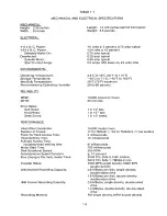
The mechanical and electrical specifications of the drive are listed in Table 1-1.
1.6
POW ER R E Q U I R E MENTS
The power requirements of the drive are listed in Table 1-2.
1.7
I NTERF A C E C IRCUIT SPECIFICATIONS
The interface circuits are designed so that a disconnected wire results in a false signal.
Levels:
True
=
+0.4 V, maximum
False
=
+2.4 V, minimum
1 . 8
IN C O M I N G IN S P E CT ION CH E C K S AN D P R O C E D U R E S
T here are two k inds of re co mmended incoming inspection checks and procedures :
s ta t i c a n d
dynamic ones.
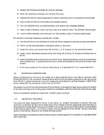
The static incoming inspection checks include the minimum steps that should be taken to ensure
that the drive is operational when received.
1-2
Summary of Contents for TM848-1
Page 32: ...HUB CENTER LINE TRACK 0 TRACK 38 TRACK 76 Figure 2 2 Hub Center Line and Track Locations 2 3 ...
Page 81: ...APPENDIX I PRINTED CIRCUIT BOARD S CHEM A T ICS AND ASSEM B LY DRAW IN G S ...
Page 88: ...APPENDIX II RECOM M E N D E D SPARE PARTS LIST ...
Page 90: ...Pi N 1 79031 001 1 082 ...


