Note
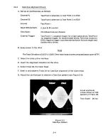
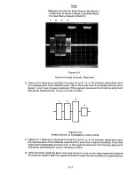
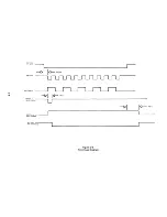
Measure the azimuth burst. Ensure that Burst 1
is less than or equal to Burst 2, and that Burst
4 is less than or equal to Burst 3.
1
2
3
4
Figure 2-9
Optimum Head Azimuth A l i g n ment
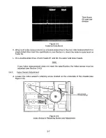
E. Figure 2-10 depicts an azimuth of exactly minus 9, 12, or 18 minutes, depending upon
the manufacturer of the diskette used. This is the lower limit of allowable azimuth error.
Bursts 1 and 2 are of equal amplitude. If this signal is observed, the Cats Eye alignment
should be checked prior to any corrective action.
3 '
Figure 2-10
Head Azimuth of Acceptable Lower Limits
F. Figure 2-11 depicts an alignment of exactly plus 9, 12, or 18 minutes, depending upon
the manufacturer of the diskette used. Bursts 3 and 4 are of equal amplitude. This is the
upper limit of allowable azimuth error. If this signal is observed, the Cats Eye alignment
should be checked prior to any corrective action.
G. After the lower head has been checked, switch to read on the upper head and observe
the azimuth pattern. Both the upper and lower heads should be within the specification.
2-1 1
Summary of Contents for TM848-1
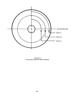
Page 32: ...HUB CENTER LINE TRACK 0 TRACK 38 TRACK 76 Figure 2 2 Hub Center Line and Track Locations 2 3 ...
Page 81: ...APPENDIX I PRINTED CIRCUIT BOARD S CHEM A T ICS AND ASSEM B LY DRAW IN G S ...
Page 88: ...APPENDIX II RECOM M E N D E D SPARE PARTS LIST ...
Page 90: ...Pi N 1 79031 001 1 082 ...


