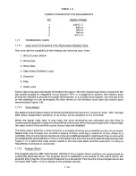
TABLE 1-4
P OW E R C O N N E C T O R PIN ASSIGN M E N T S
S u
I Vo l t a e
24V D. C.
Return
Return
Return
5V D. C.
Pin
1.17
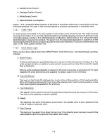
TERM IN A T E D L IN ES
1.17.1
Inp u t L i n e Terminations From Removable Resistor Pack
The drive has the capability of terminating the following input lines:
1. Write Current Switch
2. Write Data
3. Write Gate
4. Side Select (TM848-2 only)
5. Direction
6. Step
7. Head Load
These input lines are individually terminated through a 150 ohm resistor pack that is installed in the
dip socket located at i n t egrated circuit location RP1. In a single-drive system, this resistor pack
should be installed to provide the proper terminations. In a multiple-drive system, only the last drive
on the interface is to be te rminated. All other drives on the interface must have the resistor pack
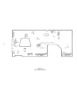
removed (see Figure 1-6).
1.17.2
D riv e S e l e c t
The Select lines provide a means of selecting and deselecting a drive. These four lines- DS1 through
DS4-allow independent selection of up to four drives attached to the controller.
W hen th e s i g na l l o gi c l e ve l i s t r u e ( l ow), the d r ive e l e c t ronics ar e a c t ivated an d t h e d r iv e i s
conditioned to respond to Step or to Read/Write commands. When the signal logic level is false (high),
the input control lines and the output status lines are disabled.
The drive select address is determined by a movable shorting plug installed on the circuit board.
Select lines one t h ro ugh four provide a m e ans of d a isy chaining a ma ximum of four drives to a
controller. Only one line can be true (low) at a time. An undefined operation might result if two or more units
are assigned the same address or if two or more select lines are in the true (low) state simultaneously (see
Figure 1-7). A select line must remain stable in the true (low) state until the execution if a Step or
Read/Write command is completed.
1.17.3
Pro g r am Shunt
The program shunt is AMP Part Number 435704-8. The program shunt positions are programmed by
cutting the particular shunt. The program shunt is installed in a dip socket. At the user's option, the
program shunt may be removed and replaced by a dip switch. Pins 8 and 9 of the program shunt are
not used. See Table 1-5 for a listing of the program shunts.
1-14
Summary of Contents for TM848-1
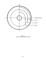
Page 32: ...HUB CENTER LINE TRACK 0 TRACK 38 TRACK 76 Figure 2 2 Hub Center Line and Track Locations 2 3 ...
Page 81: ...APPENDIX I PRINTED CIRCUIT BOARD S CHEM A T ICS AND ASSEM B LY DRAW IN G S ...
Page 88: ...APPENDIX II RECOM M E N D E D SPARE PARTS LIST ...
Page 90: ...Pi N 1 79031 001 1 082 ...

