SECTION I I I
P RINTED CIRCUIT BOAR D O P E R A T I O N
INTRODU CT ION
This section contains the interface description and the circuit board theory of operations for the
TM848 familyof disk drives. In addition, Sections 3.1 and 3.2 contain schematic diagrams of the
circuit boards Installed in the drive.
3.1
P H Y S I C A L D E S C R IPTION OF THE CIRCUIT BOARD
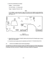
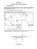
The printed circuit board is approzimately 12.50-inches long by 5.25-inches wide. Figure 3-1
contains an illustration of the placement of test points and connectors.
M3
2SOO
DCOO
0 M4
TP2
00
Rl
00 DSI
Ib 0 00 DS2
2b 0 ooDS3
35 0 00 DS4
RM
0
45 0
MC3
TP5
P 0 0
0
f
00
00
K H
0 0
PTe
0
MC200$ MCI
62 O
S
O SI
D 0
C 0
MC4 0
32
NP
OO Y
O
OO
+
00 D S 2
DSI
TPII 0 0 TP 1 2
50
TPT
OTPS
OTPIO
O
'oDL
P2
P3 P I O
P I
P I I P12
M2
00
IZ
P6
P14
TPS
Figure 3-1
Printed Circuit Board
3.2
IN T E R F A C E E L E C T R O N ICS SPECIFICATIONS
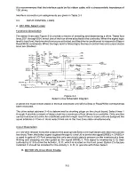
All interface signals are TTL compatible. Logic true (low) is+0.4 volt minimum. Figure 3-2 illustrates
the interface configuration. The maximum interface cable length is ten feet.
+ SV
I
I
I
I
I
T
160 OHMS
I
TWISTED PAIR
74LSD4 DR EQUIVALENT
4 TRUE
I
I
I
I
I
I
LTl16 DR EQUIVALENTg
I
I
I
I
I
I
I
~ 1 0 FEET
I
I
T RA N SMISSION LINE
I
I
I
I
I
I
I
I RECEIVER
I
I
I
I
I
Figure 3-2
Interface Configuration
Summary of Contents for TM848-1
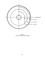
Page 32: ...HUB CENTER LINE TRACK 0 TRACK 38 TRACK 76 Figure 2 2 Hub Center Line and Track Locations 2 3 ...
Page 81: ...APPENDIX I PRINTED CIRCUIT BOARD S CHEM A T ICS AND ASSEM B LY DRAW IN G S ...
Page 88: ...APPENDIX II RECOM M E N D E D SPARE PARTS LIST ...
Page 90: ...Pi N 1 79031 001 1 082 ...


