0
0
0
0
OO
Qo
0o
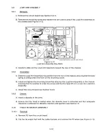
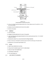
MOUNTING SCREWS 4 PLACES
Figure 5-23
Head Carriage Removal
F. Lift out the Head Carriage Assembly.
5.18.2
I ns t a l l a t ion
A. Install the carriage shaft in the carriage.
B. Using the four original mounting screws, attach the carriage shaft to the chassis.
C. Install the Stepper Motor Assembly (see Section 5.17.2).
Note
Take care not to damage the Arm Spring Assembly.
D. Plug connectors P8 and P9 into the circuit board.
E. Cable harness the Head Carriage Assembly's wires to the main wire b u n dle.
5 .18.3
Ch ec k s
A. Check the azimuth (see Section II).
B. Check the Cats Eye alignment (see Section II).
C. Check the index alignment (see Section II).
5-20
Summary of Contents for TM848-1
Page 32: ...HUB CENTER LINE TRACK 0 TRACK 38 TRACK 76 Figure 2 2 Hub Center Line and Track Locations 2 3 ...
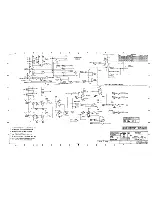
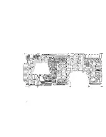
Page 81: ...APPENDIX I PRINTED CIRCUIT BOARD S CHEM A T ICS AND ASSEM B LY DRAW IN G S ...
Page 88: ...APPENDIX II RECOM M E N D E D SPARE PARTS LIST ...
Page 90: ...Pi N 1 79031 001 1 082 ...

