E. Reverify the Cats Eye alignment (see Section 2.2.1).
2.4
I NDEX S E N S O R CH ECKS AND ADJUSTMENTS
The index adjustment changes the time period from the index pulse to the start of the data. The
adjustment should be checked after the drive has been aligned (see Section 2.1.1) or when diskette
interchange errors are suspected.
2.4.1
I ndex - t o - Data Burst Check
A. Apply power to the drive.
B. Select the drive.
C. Check the spindle speed of the drive (see Section 2.1).
D. Set up an oscilloscope as follows:
Trigger:
Read Differentially:
Channel A:
Channel B:
Single-sided drives trigger on
right lead of R33 (closest to
DS2), negative edge; double-sided
drives trigger on Test Point 12,
negative edge.
A plus B, B inverted
Test Point 2
Test Point 3
50 microseconds per division
Time Base:
E. Insert an alignment diskette.
F. Seek to Track 1.
G. Select Head 00, the lower head.
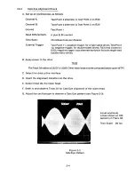
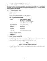
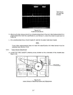
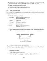
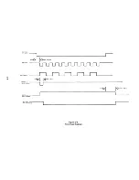
H. Ensure that the index-to-data burst occurs at 200 microseconds k 100 microseconds from
the leading edge of the index pulse (see Figure 2-5).
I. For double-sided drives, select Head 01 and repeat the steps above.
Note
Head 01 should meet the same specification.
J. If either Head 00 or Head 01 does not meet the specifications, adjust the index sensor (see
Section 2.4.2.).
2-6
Summary of Contents for TM848-1
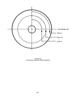
Page 32: ...HUB CENTER LINE TRACK 0 TRACK 38 TRACK 76 Figure 2 2 Hub Center Line and Track Locations 2 3 ...
Page 81: ...APPENDIX I PRINTED CIRCUIT BOARD S CHEM A T ICS AND ASSEM B LY DRAW IN G S ...
Page 88: ...APPENDIX II RECOM M E N D E D SPARE PARTS LIST ...
Page 90: ...Pi N 1 79031 001 1 082 ...

