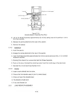
TRIGGER HOLD DOWN SCREW
EJECTOR
IIIIIII
IIIII
III
II
PIVOT BAR
EJECTOR SPRING
T RIGGER ASSEM B L Y
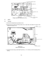
Figure 5-18
Diskette Ejector Assembly Key Parts
D. Lift up the Bridge Assembly approximately two inches, taking care not to pull the L. E. D.'s
from their sockets.
E. Release the spring attached to the rear of the ejector.
F. Remove the ejector.
5 .14.2
Ins t a l l a t io n
A. Insert the ejector.
B. Engage the spring attached to the rear of the ejector.
C. Insert the Bridge Assembly approximately two inches, taking care to put the L. E. D.'s in their
respective sockets.
D. Reinstall the original four screws that hold the Bridge Assembly.
E. Push on the lever. Reinstall the retaining screw. Insert the small plug in the door lever.
F. Reinstall the circuit board (see Section 5.3.1).
5 .14.3
Ch ec k s
A. Insert a work diskette into the drive.
B. Ensure that the diskette stays in prior to being closed.
C. Close and open the diskette lever.
D. The diskette should eject.
E. If not, see Section 5.4.
5 .15
LO A D R E S I S TOR ASS E M B L Y
5-1 5
Summary of Contents for TM848-1
Page 32: ...HUB CENTER LINE TRACK 0 TRACK 38 TRACK 76 Figure 2 2 Hub Center Line and Track Locations 2 3 ...
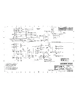
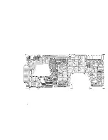
Page 81: ...APPENDIX I PRINTED CIRCUIT BOARD S CHEM A T ICS AND ASSEM B LY DRAW IN G S ...
Page 88: ...APPENDIX II RECOM M E N D E D SPARE PARTS LIST ...
Page 90: ...Pi N 1 79031 001 1 082 ...

