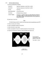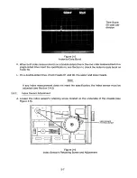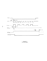
Time Scale:
50 usec per
division
Figure 2-5
Index-to-Data Burst
K. When both index measurements on a double-sided drive or the one index measurement on a
single-sided drive meet the specifications, see Section H, check the index-to-data burst on
Track 76.
L. On a double-sided
drive,
check Heads 01 and 00,
the upper and lower heads.
Note
If any index measurement does not meet the specification, the index sensor must be
adjusted (see Section 2.4.2).
2.4.2
In dex S e n s o r Adjustment
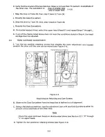
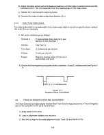
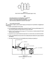
A. Loosen the index sensor's retaining screw located on the underside of the chassis (see
Figure 2-6).
o
o
INDEX SENSOR
RETAINING SCREW
0
0
6' - 0-~ e
(
o
J
Figure 2-6
Index Sensor's Retaining Screw and Adjustment
2-7
Summary of Contents for TM848-1
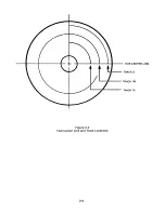
Page 32: ...HUB CENTER LINE TRACK 0 TRACK 38 TRACK 76 Figure 2 2 Hub Center Line and Track Locations 2 3 ...
Page 81: ...APPENDIX I PRINTED CIRCUIT BOARD S CHEM A T ICS AND ASSEM B LY DRAW IN G S ...
Page 88: ...APPENDIX II RECOM M E N D E D SPARE PARTS LIST ...
Page 90: ...Pi N 1 79031 001 1 082 ...

