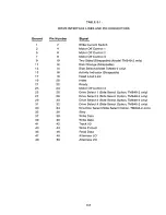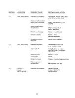
TABLE 3-1 •
D RIVE INTERFACE LINES AND PIN CON N E C T O R S
Ground
Pin Number
1
3
5
7
9
2
4
6
8
10
12
14
16
18
20
22
24
26
28
30
32
34
36
38
40
42
44
46
48
50
Signal
Write Current Switch
Motor Off Control 1
Motor Off Control 2
Motor Off Control 3
Two Sided (Strappable) (Model TM848-2 only)
Disk Change (Strappable)
Side Select (Model TM848-2 only)
Activity Indicator (Strappable)
Head Load Line
Index
Ready
Motor Off Control 4
Drive Select 1 (Side Select Option, TM848-2 only)
Drive Select 2 (Side Select Option, TM848-2 only)
Drive Select 3 (Side Select Option, TM848-2 only)
Drive Select 4 (Side Select Option, TM848-2 only)
Direction Select (Side Select Option, TM848-2 only)
Step
Write Data
Write Gate
Track 00
Write Protect
Read Data
Alternate I/O
Alternate I/O
11
13
15
17
19
21
23
25
27
29
31
33
35
37
39
41
43
45
47
49
3-3
Summary of Contents for TM848-1
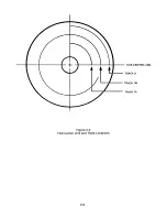
Page 32: ...HUB CENTER LINE TRACK 0 TRACK 38 TRACK 76 Figure 2 2 Hub Center Line and Track Locations 2 3 ...
Page 81: ...APPENDIX I PRINTED CIRCUIT BOARD S CHEM A T ICS AND ASSEM B LY DRAW IN G S ...
Page 88: ...APPENDIX II RECOM M E N D E D SPARE PARTS LIST ...
Page 90: ...Pi N 1 79031 001 1 082 ...


