5.1 5.1 Re m oval
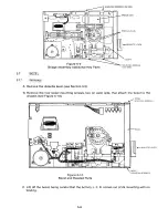
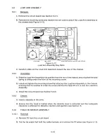
A. Remove P5 from the circuit board.
B. Remove the circuit board (see Section 5.3.1).
C. Remove the two mo u nting screws that attach the Load Resistor Assembly to the chassis.
D. Unsolder the wires to the load resistors (see Figure 5-19).
E. Mark or identify these wires so that they can be put back in the same location.
MO U N TING SCREWS, 2
LOAD RESISTOR ASSEMBLY.
SOLDER JOINT, 4 PLACES
IIlll
ll
ll
ll
fll
ll
l
0
0
o o
o
0
p
0o
Jl
Fig ure 5-1 9
Load Resistor Assembly and Key Parts
5.15.2
I ns t a l l a t ion
A. Solder the wires back in the same place at which they were originally.
B. Mount the Load Resistor Assembly onto the chassis using the two original mounting screws.
C. Install the circuit board (see Section 5.3.2).
D. Plug P5 into the circuit board.
5 .15.3
C hec k s
A. Enable the drive through the interface logic.
B. Step the drive to Track 00.
C. Step the drive to Track 76.
D. Do the C. E. alignment verification procedure (see Section II).
5-16
Summary of Contents for TM848-1
Page 32: ...HUB CENTER LINE TRACK 0 TRACK 38 TRACK 76 Figure 2 2 Hub Center Line and Track Locations 2 3 ...
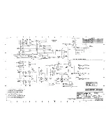
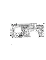
Page 81: ...APPENDIX I PRINTED CIRCUIT BOARD S CHEM A T ICS AND ASSEM B LY DRAW IN G S ...
Page 88: ...APPENDIX II RECOM M E N D E D SPARE PARTS LIST ...
Page 90: ...Pi N 1 79031 001 1 082 ...


