Peripheral Equipment
243
6.1.4 Data
port
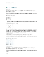
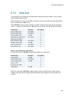
The data port(s) are implemented as Data Communications Equipment (DCE). The connectors
used are female 9-pin D-subs.
NOTE! Data port 2 is used by both Wave II Camera and Precision HD Camera and has different
pin-out scheme for the different use.
The TANDBERG main camera is normally connected to data port 2 and pin number 4 provides
12V DC / 1 Amps to the main camera. Otherwise the pin-outs for both data ports are the same.
Signal name
Direction
Pin number
Carrier detect, CD
From DCE
1
Receive data, RXD
From DCE
2
Transmit data, TXD
To DCE
3
Data terminal ready, DTR
From DCE
4
Signal ground, GND
5
Data set ready, DSR
From DCE
6
Ready to send, RTS
To DCE
7
Clear to send, CTS
From DCE
8
Ring indicator, RI
From DCE
9
Data Port 2 with Precision HD Camera
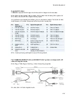
Pin-outs for the THSI (TANDBERG High Speed Interface) on data port 2:
Signal name
Direction
Pin number
Video LVDS +
To DCE
1
Receive data, RXD
From DCE
2
Transmit data, TXD
To DCE
3
Power, +12V
4
Signal ground, GND
5
Video LVDS -
To DCE
6
NOTE! The enclosed TANDBERG Camera Cables must be used! Do not use other camera
cables as this might cause problems with the transfer of video signals from the Precision HD
Camera.
Summary of Contents for 6000 MXP Profile
Page 14: ......
Page 145: ...General Use 131 PC Presentation shown in Wide stretched mode ...
Page 205: ...General Use 191 Voice Switched mode ...
Page 268: ...TANDBERG 6000 MXP 254 ...
Page 293: ...Appendices 279 ...
Page 297: ...Appendices 283 Top view ...
Page 300: ...TANDBERG 6000 MXP 286 Dimensions Front view Side view Rear view Underside view ...
Page 314: ...TANDBERG 6000 MXP 300 Appendix 17 Dimensions Dimensions with the Precision HD Camera ...
Page 315: ...Appendices 301 ...
Page 317: ...Appendices 303 Top view 50 monitor ...
Page 318: ...TANDBERG 6000 MXP 304 Codec ...
Page 320: ...TANDBERG 6000 MXP 306 ...


