


Micro Weld Heads
CWS
−
D100
−
B Welding System
2005 Swagelok Company, All rights reserved
September 2005
4-10
3.
Insert the first work piece, butting the weld end against
the gage surface. Close and latch that side of the fixture.
Make sure that the latch is fully closed against the body
of the fixture. See Figure 4-13.
4.
Remove the centering gage.
5.
Open the other side of the fixture and insert the second
work piece. Butt the weld ends together. Close and latch
that side.
6.
Check the weld joint for proper fit and alignment. See
Figure 4-13. Verify that the latches are fully closed. See
Figure 4-13 (Series 4) or Figure 4-14 (Series 8).
7.
Connect the purge gas line to the work pieces. See
Figure 2-6 in Section 2,
Installation
.
8.
Open the shut-off valve in the purge gas line.
9.
Set the flow meters according to the weld procedure
guideline for both the shielding and internal purge gas.
Table 4-1
Shield Gas Flow Rates (Argon)
Weld Head Series
std ft
3
/h (L/min)
4MH
8 to 10 (4 to 4.7)
8MH
15 to 20 (7.1 to 9.4)
The length of time for internal purge before welding
depends on the internal volume and length of the work
piece to be welded. See Appendix G,
Gas Flow
Rate Tables
.
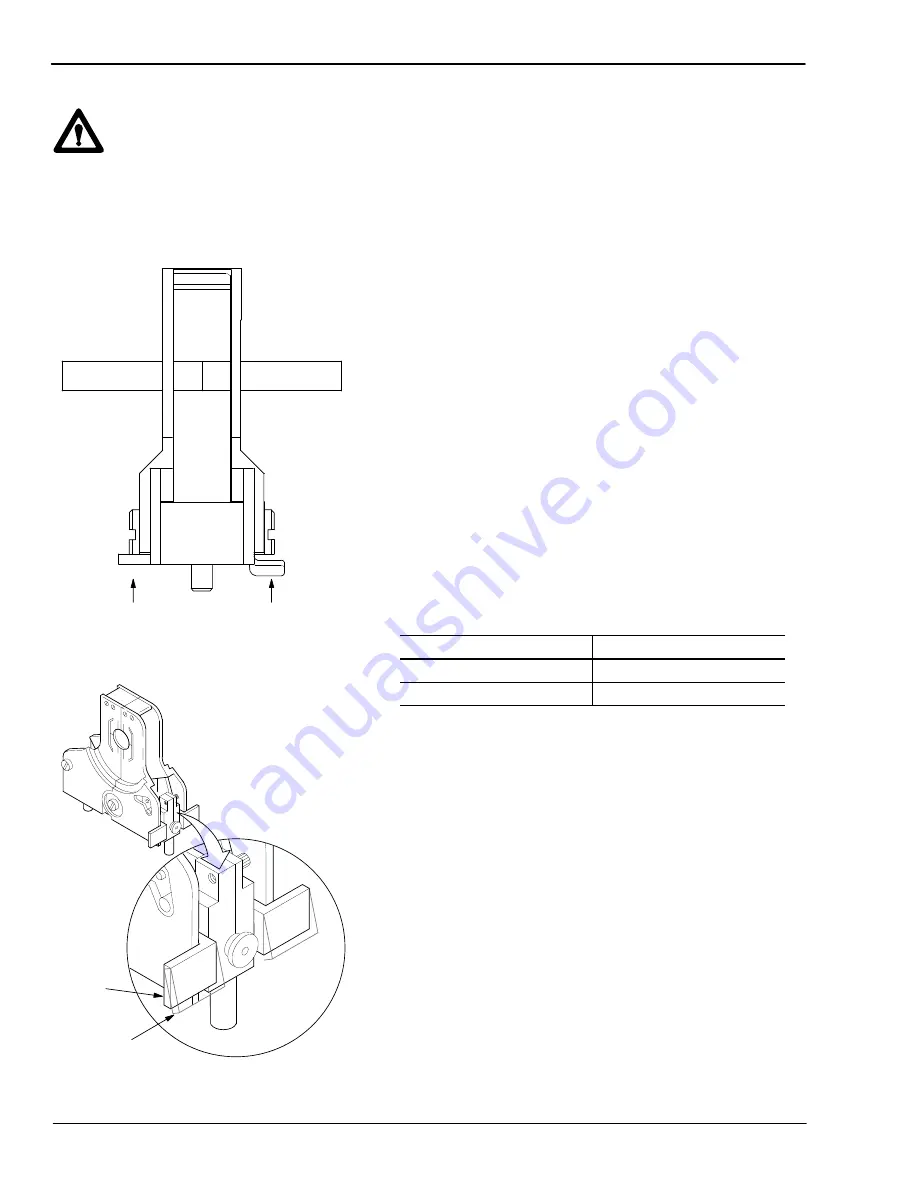
Caution!
When closing the fixture,
be sure the moving side
of the fixture engages
into the small groove on
the stationary side of
the fixture.
Figure 4-13 Checking the Weld Joint
(Series 4 Fixture)
Correct
Wrong
Figure 4-14 Proper Latch Position
(Series 8 Fixture)
Correct
Wrong