Swagelok CWS-D100-1B User Manual Download Page 76

Operation

CWS

D100

B Welding System

2005 Swagelok Company, All rights reserved

September 2005

3-28

4.

Restore power to the SWS by turning the
circuit breaker on.

5.

Press 

STOP/RESET

 to return the rotor to the

home position and visually inspect the
rotor smooth rotation.

Preparing the Work

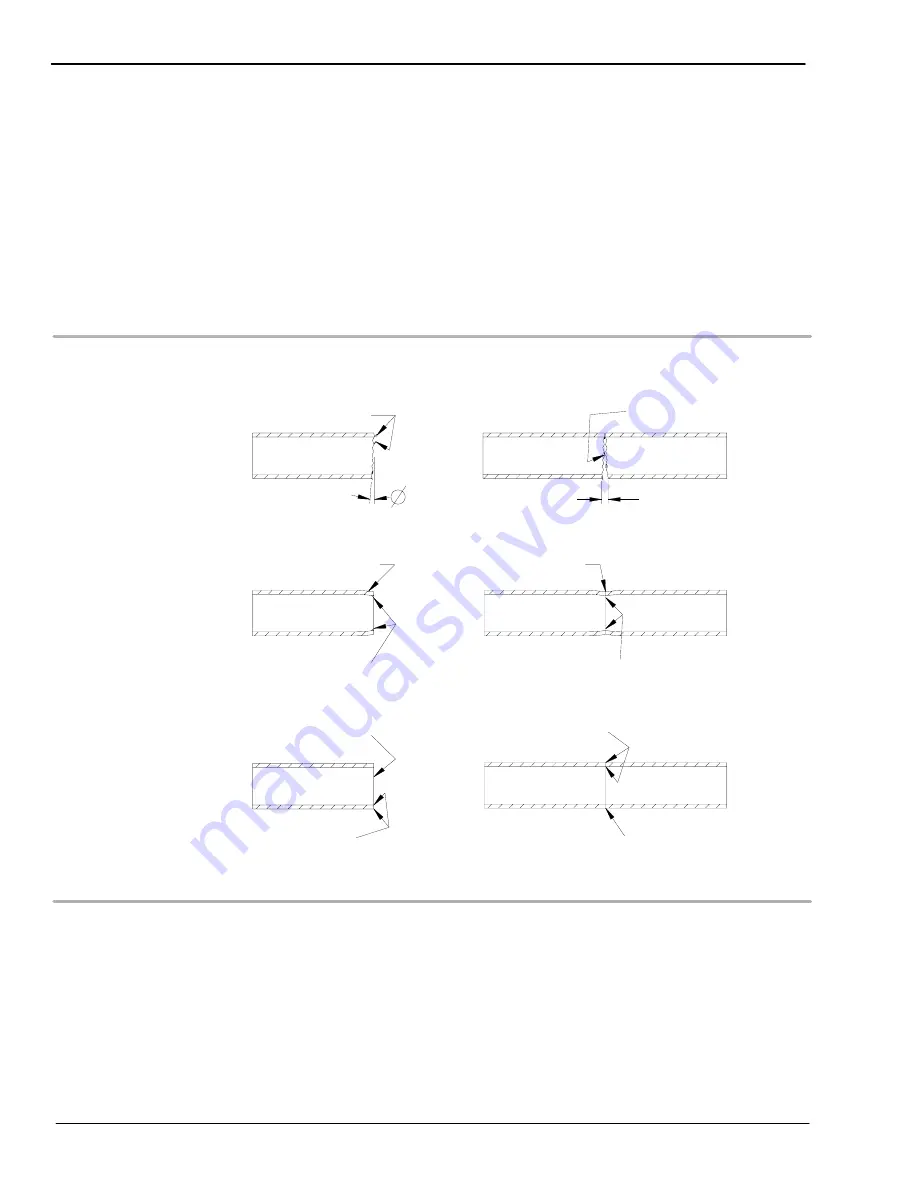
Refer to Figure 3-20. Prepare the tube pieces to be welded.

Figure 3-20  Tube Preparation

Method

Result

Hack Saw Cut

Burrs

Gap

Burrs in

Flow Path

Tube Cutter

   End Roller in by Cutter

Burrs

Reduced Flow Area

Irregular Wall 

Tube Facing Tool

Square Corners

Face Perpendicular

No Gaps

Smooth Transition

Blade and Roller

at Wall Faces

to Axis

Thickness

Tubing must be square and burr-free to ensure
repeatable, high-quality autogenous fusion welds. Cut
the tubing to length with a hacksaw or tube cutter. Face
the tube ends with a lathe or a portable facing tool.
Deburr the ends, making sure that both the inside and
outside diameters are square and burr-free. Clean the
tube ends using an appropriate solvent.

Summary of Contents for CWS-D100-1B

Page 1: ...www swagelok com US E R S MA N U A L CWS D100 1B CWS D100 2B W E L D I N G S Y S T E M...

Page 2: ...from defects in material and workmanship for twelve months from the date of purchase The purchaser s remedies shall be limited to replacement and installation of any parts that fail through a defect...

Page 3: ...c Welding 1 2 Principles of the GTAW Process 1 2 GTAW Process Advantages 1 2 Process Variables 1 3 System Components 1 4 The SWS D100 Power Supply 1 4 The Weld Head 1 5 Fixture Blocks 1 6 Overview of...

Page 4: ...s 3 6 Status Indicator Lights 3 8 Digital Displays 3 9 SWS Modes of Operation 3 9 Operational Mode 3 12 Program Mode 3 17 Test Mode 3 22 Installing the Electrode in the Series 5 10 20 Weld Head 3 26 S...

Page 5: ...p 4 8 Fixturing the Work 4 9 Connecting the Micro Weld Head to the Fixture 4 11 Considerations During Welding 4 13 Using the Optional Bench Mounting Bracket 4 14 Series 4 Bench Mount Bracket 4 14 Seri...

Page 6: ...7 Troubleshooting Introduction 7 1 Swagelok Welding System SWS Repair Procedure 7 1 Repair Replacement Instructions 7 2 Appendix A Glossary Appendix B Optional Equipment SWS Remote Pendant B 2 Weld H...

Page 7: ...LDING D 5 SERIES 20 WELD HEAD TUBE WELDING D 6 Appendix E Arc Gap Gage Setting Tables Wall Thickness and Arc Gap E 1 Weld Head Arc Gap Gage Setting Tables E 2 Arc Gap Gage Setting Tables for Swagelok...

Page 8: ...Table of Contents CWS D100 B Welding System 2005 Swagelok Company all rights reserved September 2005 TOC 6...

Page 9: ...a moment to fill out the warranty information form as well as the information listed below Keep this information available in case you need to contact your Swagelok representative Power Supply Model N...

Page 10: ...Foreword CWS D100 B Welding System 2005 Swagelok Company all rights reserved September 2005 ii...

Page 11: ...age to the equipment or other property WARNING Statements identify conditions or practices that could result in personal injuries or loss of life Symbols The following symbols are used in this manual...

Page 12: ...D Verify that the power supply is properly grounded before use Make sure the power cord is plugged into a properly wired and grounded receptacle D Follow local electrical codes and the guidelines in t...

Page 13: ...air and lower the oxygen level causing injury or death Be sure the breathing air is safe D Do not weld in locations near degreasing cleaning or spraying operations The heat and rays of the arc can rea...

Page 14: ...approved ear protection if noise level is high WELDING can cause fire or explosion Welding on closed containers such as tanks drums or pipes can cause them to blow up The hot work piece and hot equipm...

Page 15: ...lag open flames sparks and arcs D Install cylinders in an upright position by securing to a stationary support or cylinder rack to prevent falling or tipping D Keep cylinders away from any welding or...

Page 16: ...ing the work piece weld head and electrode can be extremely hot and may cause burns MAGNETIC FIELDS can affect pacemakers D Pacemaker wearers keep away D Wearers should consult their doctor before goi...

Page 17: ...nd cover the system when not in use D Weld Heads Disconnect the weld head completely from the power supply prior to servicing User service including cleaning or component replacement is limited to tho...

Page 18: ...Foreword CWS D100 B Welding System 2005 Swagelok Company all rights reserved September 2005 x Power Supply Warning Label This warning label is affixed to the power supply...

Page 19: ...Welding Society 550 N W LeJeune Rd Miami FL 33126 www aws org 3 CGA Publication P 1 Safe Handling of Compressed Gases in Cylinders Compressed Gas Association 4221 Walney Road 5th Floor Chantilly VA 20...

Page 20: ...Foreword CWS D100 B Welding System 2005 Swagelok Company all rights reserved September 2005 xii...

Page 21: ...1 Introduction SWS D100 The Swagelok Welding System SWS is a versatile portable and easy to use orbital welding system This section includes D gas tungsten arc welding D system components D overview...

Page 22: ...between the tip of the electrode and the work Heat generated by the arc melts the base metal Once the arc and weld puddle are established the electrode moves along the joint and the arc progressively...

Page 23: ...tungsten electrode and the work Arc voltage is affected by the following D arc current D shape of the tungsten electrode tip D type and purity of shielding gas D arc length distance between the elect...

Page 24: ...00 Power Supply The power supply features microcontroller electronics and closed loop circuitry to precisely control output current Simplified controls and displays provide efficient programming and m...

Page 25: ...in the weld head sends precise feedback to the power supply to control the speed of the rotor All moving parts in the weld head mount in low friction devices to provide smooth consistent operation A s...

Page 26: ...e fixture blocks offers increased productivity Each fixture block is designed to accommodate a range of work piece sizes A unique and patented Universal Collet Insert UCI fits into the fixture block t...

Page 27: ...d in the fixture block using a centering gage Since the fixture block is not part of the weld head multiple fixture blocks can be used to maximize weld setup efficiency The weld head cable assembly at...

Page 28: ...Introduction CWS D100 B Welding System 2005 Swagelok Company all rights reserved September 2005 1 8 Figure 1 5 SWS D100 Front Panel Controls...

Page 29: ...ld to the time the power supply must remain idle to cool The 10 minute cycle is a recognized welding industry standard It represents the maximum weld time allowed with the balance of the 10 minute cyc...

Page 30: ...TR A motor module Requires SWS 20TFB A Table 1 6 Standard Fixture Blocks Model OD Capacity Minimum Weld Extension Length CWS 4MFA 1 16 to 1 4 in 3 to 6 mm 1 4 in 6 mm SWS 8MFA 1 4 to 1 2 in 6 to 12 mm...

Page 31: ...DA manual actuator only Table 1 8 Collets Model OD Capacity Comments CWS 5UCI 1 8 in to 5 8 in 3 mm to 16 mm tubing add mm suffix for metric sizes CWS 5UFCI 95 n a fixture collets to hold adapter ins...

Page 32: ...erall length of 0 77 in 20 mm or less with captured female nut SS 4 VCR 1 CWS 5MSVCR 04 6LV 4 SVCR 3 with captured male nut SS 4 SVCR 4 CWS 5FSVCR 04 6LV 4 SVCR 3S 6LV 4 SVCR 3 with captured female nu...

Page 33: ...his section describes the procedures necessary for installing the Swagelok Welding System SWS This section includes D tools and accessory requirements D electrical requirements D unpacking and inspect...

Page 34: ...s Power Supply Secondary Solenoid Bypass Plug Yes Power Supply Dial Digital Calipers or Micrometer No Purge Connector s No Shielding Purge gas lines 1 No Shielding Purge Gas Source 2 No Pressure Regul...

Page 35: ...ical requirements for the power supply D All wiring and related components must be installed according to local and National Electrical Codes D The power supply must be grounded D A dedicated electric...

Page 36: ...al CWS MANUAL D100B 1 Denotes Model Denotes Language Remove the contents of the shipping container by performing the following steps 1 Remove the following items D Swagelok Welding System User s Manua...

Page 37: ...m lined shipping container D weld head assembly D arc gap gage D electrode package D tool package 1 Inspect the container for damage 2 Remove the components from the container 3 Check the items for an...

Page 38: ...1 Place the power supply in a position such that the front and rear panel controls are easily accessible 2 Locate the power cord Insert the cord into the polarized receptacle on the rear of the power...

Page 39: ...power supply See Figure 2 4 The four connectors on the cable are D fixture D electrode red D work green D weld head shielding gas Connect the four connectors to the rear panel of the power supply by...

Page 40: ...connection is the negative output terminal of the weld head 4 Insert the green connector into the socket on the rear panel labelled WORK Twist the connector 1 4 turn clockwise to lock it into place Th...

Page 41: ...educes oxidation or contamination to the weld puddle tungsten electrode and Heat Affected Zone HAZ There are two types of gas delivery systems commonly used D typical Gas Delivery System Refer to the...

Page 42: ...he following precautions D Ensure that the gas storage container s are secured before using them D Ensure all connections are tight and do not leak D Use only a Swagelok single ended shut off Quick Co...

Page 43: ...S Fixture Block Flow Meter for Internal Purge Gas Range 0 std ft3 h to 30 std ft3 h Swagelok Union or Reducing Union with Nylon Ferrules or Ultra Torr for Purge Gas Restriction Swagelok Union or Reduc...

Page 44: ...ide 12 V to control the secondary solenoid For the gas delivery system using a secondary shielding gas solenoid valve locate the D secondary solenoid bypass plug D secondary shielding gas solenoid val...

Page 45: ...2 7 Optional Gas Delivery System Supply Manifold Secondary Solenoid Valve Internal Purge Gas Flow Meter Secondary Solenoid Bypass Plug Weld Head Shielding Gas Flow Meter Inert Gas Cylinder SWS Fixtur...

Page 46: ...eaker After a 2 second to 4 second delay the following is displayed D Blinking decimal point followed by a zero in the Average Current and Average Voltage displays on the power supply front panel See...

Page 47: ...osition in the head See Figure 2 11 D For the micro head the rotor should make one complete rotation in the head 5 Press STOP RESET on the front panel to return the rotor to its home position 6 Turn o...

Page 48: ...Installation CWS D100 B Welding System 2005 Swagelok Company All right reserved September 2005 2 16...

Page 49: ...ntering the weld parameters D setting the shield gas flow D starting and completing the weld The description of the welding process in this section uses a weld procedure guideline based on tubing with...

Page 50: ...Purge pushbutton 17 Rotor Jog pushbutton 18 Print pushbutton 19 Stop Reset pushbutton 20 Status indicator lights 21 Remote Pendant connector 12 20 7 8 9 10 16 17 18 19 14 13 11 1 2 3 4 5 6 15 21 You o...

Page 51: ...D MAINTENANCE Low Amps sets the minimum current output used during the weld cycle This is the current level required to D maintain the arc D provide enough background heat to maintain the weld puddle...

Page 52: ...h is maintained during this time D The rotor does not move during this time D WELD TIME Seconds is the actual welding time at the average current During the weld time the output current cycles between...

Page 53: ...ork is cooling D ROTOR SPEED of Max Speed is expressed as a percentage of the maximum RPM that the rotor can attain A rotor speed setting of 99 gives the maximum RPM for the weld head See Table 3 1 Ta...

Page 54: ...peed when traveling to the home position regardless of the programmed rotor speed When not welding pushing STOP RESET causes the rotor to rotate as shown in Table 3 2 Table 3 2 Stop Reset Rotor Travel...

Page 55: ...pushbutton to stop the rotor ROTOR JOG can be used to position the rotor for electrode replacement or adjustment The rotor will move at the speed defined by the ROTOR SPEED rotary switches D PRINT cau...

Page 56: ...is not connected the indicator light is on The power supply will not start a weld cycle when this indicator light is on D Prepurge indicates the prepurge cycle is active The Prepurge cycle occurs pri...

Page 57: ...amming and displaying message codes See SWS Modes of Operation SWS Modes of Operation The front panel controls serve two purposes In addition to controlling the weld parameters and weld sequences the...

Page 58: ...Rotor Speed 5 to 99 1 or 5 Caution 1 Disable 12 to 19 Factory use Not used 20 Resettable weld counter 0 to 9999 Program mode Programmable 21 Automatic print counter 0 to 99 Program mode Programmable...

Page 59: ...o 59 Factory use Not used 60 Non resettable weld counter Program mode Information only 61 Arc start attempts Program mode Information only 62 System serial number Program mode Information only 63 Syst...

Page 60: ...e display is accompanied by flashing status indicator lights a disable condition exists If not the code display indicates a caution condition Message codes 1 to 11 refer to the front panel rotary swit...

Page 61: ...rotary switch has the questionable value Interpreting the Message Codes The power supply shows the switch setting problem by displaying the switch code on the Average Voltage display Codes 1 to 11 us...

Page 62: ...right indicates above maximum B Multiple Disable or Caution Conditions The power supply displays multiple errors on the digital displays one after another Each message code is displayed for a moment...

Page 63: ...ition occurs when a temperature sensor inside the power supply detects a buildup of heat that exceeds a predefined limit The power supply is disabled until the internal temperature drops to a safe lev...

Page 64: ...by developing a proper weld procedure guideline EXAMPLE 2 Caution Condition A weld procedure guideline is keyed in and Prepurge is set to zero seconds You may wish to use a continuous purge so the pre...

Page 65: ...to enter program mode 1 Press and hold DOWNSLOPE 2 Press and hold ROTOR JOG 3 Release both pushbuttons at the same time The status indicator lights begin to sequence up and down indicating that the p...

Page 66: ...s 31 Time minutes Yes 32 Date month Yes 33 Date day Yes 34 Date year Yes 35 Date printing format Yes 60 Nonresettable weld counter No 61 Arc start attempts No 62 System serial number No 63 System soft...

Page 67: ...n Appendix B Optional Equipment for an example of the printout 22 Enable signal polarity The Enable signal one of the BNC data recording outputs described in Appendix B Optional Equipment has a select...

Page 68: ...5 seconds Its maximum value is 999 999 Code 61 is a counter tracking arc start attempts Any attempt to start an arc will increment the counter This counter is also not resettable The value will be gre...

Page 69: ...lue 1 Press and hold DOWNSLOPE 2 Press and hold ROTOR JOG 3 Release both pushbuttons at the same time The SWS is now in program mode 4 Enter 20 into ROTOR SPEED 5 Enter 10 into ARC START Enter 00 into...

Page 70: ...ys and the optional remote operator pendant Table 3 6 Test Mode Code Numbers Code No Description Programmable 97 Test switches pushbuttons n a 98 Test indicator lights displays n a Test Descriptions 9...

Page 71: ...at has a non zero value When the power supply is switched to the test mode the digital displays indicate the value keyed into IMPULSE For example if IMPULSE is set to 45 0 the display appears as shown...

Page 72: ...tons and corresponding status indicator lights are shown in Table 3 7 Table 3 7 Pushbutton Test Reference Pushbutton Lights Illuminated Start Fixture and Rotor Downslope Prepurge Purge Start Rotor Jog...

Page 73: ...1 Exit Test code 97 by pressing DOWNSLOPE and STOP RESET simultaneously then release both pushbuttons 2 Enter 98 into ROTOR SPEED Test code 98 verifies the front panel lights and displays All front pa...

Page 74: ...Electrode into a Rotor 1 Press STOP RESET The rotor makes one half of a revolution 180 for the Series 5 10 and 20 weld head assuming that the weld head is not attached to a fixture block 2 Verify tha...

Page 75: ...Gap Gage Setting Tables Find the actual outside diameter nearest to your measurement 3 Adjust the arc gap gage to match the setting from the table or weld procedure guideline See Figure 3 18 B 4 To c...

Page 76: ...Saw Cut Burrs Gap Burrs in Flow Path Tube Cutter End Roller in by Cutter Burrs Reduced Flow Area Irregular Wall Tube Facing Tool Square Corners Face Perpendicular No Gaps Smooth Transition Blade and...

Page 77: ...side diameter Selecting the Fixture Block and Collets 1 Select the fixture block that accepts the outside diameter of the tube to be welded See Table 1 6 in Section 1 Introduction 2 Select the proper...

Page 78: ...The centering gage must span the width of the collet See Figure 3 23 2 Butt one work piece against the centering gage See Figure 3 24 A 3 Lock down the top side plate See Figure 3 24 B 4 Remove the c...

Page 79: ...5 3 31 5 Butt the second work piece against the first work piece and lock down the top side plate See Figure 3 25 6 Inspect 360 around the weld joint for fit and alignment If the alignment is not corr...

Page 80: ...allation Connect the internal purge gas line to the work pieces 1 Set the internal purge gas flow meter depending on the inside diameter of the work pieces See Appendix G Gas Flow Rate Tables 2 Open t...

Page 81: ...head is properly attached A sensor in the weld head signals the power supply when the fixture block is connected Fixture turns off and the power supply is ready to weld The safety interlock feature is...

Page 82: ...ever on the weld head counter clockwise until it stops See Figure 3 26 2 Insert the weld head into the fixture block See Figure 3 27 A 3 Rotate the locking lever clockwise to secure the weld head See...

Page 83: ...elok representative with your specific requirements The weld procedure guideline listed in Table 3 9 is based on 1 2 in tubing with a 0 049 in wall thickness Table 3 9 Sample Weld Procedure Guideline...

Page 84: ...urrent and low amp current In the example shown at the right the current control settings are D IMPULSE 58 8 A D MAINTENANCE 17 6 A D IMPULSE RATE 10 pulses per second D IMPULSE WIDTH 35 In this case...

Page 85: ...10 to 20 4 7 to 9 4 20 B 20 to 40 9 4 to 18 8 Set the flow to the higher rates when welding at high current levels Starting and Completing the Weld 1 Check the following before starting the weld D All...

Page 86: ...ostpurge Rotor remains on during Weld Time and Downslope and until the rotor returns to the home position after welding Average Current LED Display Compare the value shown on the display with the aver...

Page 87: ...locking lever on the weld head housing 4 Remove the weld head from the fixture block If it is difficult to remove the weld head release one of the side plate lever cams 5 Remove the internal purge ga...

Page 88: ...e fixture block 6 Align the work pieces in the fixture block 7 Connect the internal purge gas line to the work piece to be welded and set the flow meter 8 Press PURGE and set the shield gas flow 9 Pre...

Page 89: ...pieces from 1 16 in to 1 4 in 3 mm to 6 mm OD and is available in both rigid drive and flexible drive configurations The Series 8 Micro Weld Head can weld work pieces from 1 4 in to 1 2 in 6 mm to 12...

Page 90: ...edures The procedures unless noted are the same for all micro weld heads Most figures in this section show the Series 4 Rigid Drive Micro Weld Head Topics common to all weld heads are not covered in t...

Page 91: ...lows the tool to be secured by a key chain Installing the Motor Module Connect the motor module to the power supply the same way as a Series 5 10 20 Weld Head 1 Turn off the power supply circuit break...

Page 92: ...ld head must be aligned so that it meshes with the drive pins on the motor module housing 2 Locate the shielding gas port on the micro weld head and verify that the O ring is in place See Figure 4 5 T...

Page 93: ...at the home position The opening in the rotor aligns to the opening in the micro weld head housing If not disconnect the weld head and repeat the procedure A B Figure 4 6 Connecting Weld Head and Mot...

Page 94: ...ometry 2 Turn off the power supply circuit breaker on the rear panel See Figure 4 3 3 Disconnect the micro weld head from the motor module 4 Manually turn the rotor drive gear shown in Figure 4 4 unti...

Page 95: ...ode through the ceramic insulator and into the rotor to its full insertion depth Make sure the sharp tip of the electrode is pointing out See Figure 4 8 B 7 Tighten the clamping screw sufficiently to...

Page 96: ...e to the top of the adjustment screw See Figure 4 9 B 5 Insert the arc gap gage into the micro weld head rotor opening 6 Hold the micro weld head so that the electrode tip is pointing down Loosen the...

Page 97: ...Insert the gage into the fixture See Figure 4 11 The orientation of the fixture does not matter 2 Open the fixture side facing the labeled side of the centering gage by rotating the latch 90 See Figur...

Page 98: ...14 Series 8 7 Connect the purge gas line to the work pieces See Figure 2 6 in Section 2 Installation 8 Open the shut off valve in the purge gas line 9 Set the flow meters according to the weld procedu...

Page 99: ...the latch levers See Figure 4 15 B The micro weld head assembly and the work are ready for welding 2 Press PURGE to begin the shielding gas flow The shielding gas should remain on at all times when us...

Page 100: ...s CWS D100 B Welding System 2005 Swagelok Company All rights reserved September 2005 4 12 Figure 4 15 Placing the Fixture on the Micro Weld Head Latch Springs 2 B Latch Spring Captures Button Keepers...

Page 101: ...ghtly louder compared to other Swagelok weld heads This is due to the reduced size of the fixture D You may notice a clicking sound during the downslope cycle This is normal The fixture contracts slig...

Page 102: ...rmine the mounting orientation of the bracket on the workbench See Figure 4 17 Secure the bracket to the workbench Make sure the latch is accessible 2 Open the latch on the side of the bracket 3 Slide...

Page 103: ...er screws 2 Secure the adapter screw with a 1 4 in wrench or the micro fixture tool See Figure 4 18 B 3 Repeat steps 1 and 2 for the remaining latch bracket screw Verify the latch bracket remains secu...

Page 104: ...served September 2005 4 16 6 Secure the weld head using the two knurled thumb nuts supplied with the bench mounting bracket Keep the thumb nuts on the adapter screws when not using the bench mount bra...

Page 105: ...s you may need to adjust the welding parameters You start with the weld procedure guideline worksheet found on page 5 10 The steps in the worksheet show you how to develop the speed current and timing...

Page 106: ...eet found on page 5 9 Determining the Work Specifications 1 Determine the outside diameter 1 2 in of the tubing or fitting at the weld joint 2 Determine the wall thickness 0 049 in of the tubing or fi...

Page 107: ...to 12 2 96 1 04 to 1 40 2 54 16 to 19 2 12 1 42 to 1 65 2 12 22 to 25 1 69 1 66 to 2 00 1 69 25 to 38 1 69 2 03 to 2 28 1 69 40 to 52 1 27 2 30 to 2 76 1 27 2 Refer to the Rotor Speed switch setting...

Page 108: ...etting For example for a wall thickness of 0 049 in 1 2 0 049 in 1000 58 8 A d Set IMPULSE 58 8 according to the result of the formula in step 3 c 4 Calculate the Maintenance a Locate the wall thickne...

Page 109: ...3 1 168 to 2 108 35 0 084 to 0 109 2 133 to 2 769 50 b Set IMPULSE WIDTH 35 according to Table 5 5 Note If the IMPULSE is greater than 99 9 A set the IMPULSE to 99 9 However use the actual value to ca...

Page 110: ...wall thickness 0 049 in and the corresponding D factor in Table 5 6 Table 5 6 Wall Thickness and D Factor Wall Thickness Range in mm D Factor 0 015 to 0 045 0 381 to 1 143 0 3 0 046 to 0 083 1 168 to...

Page 111: ...multiply the seconds per revolution by two and set WELD TIME according to that result For example since the tubing in this example has an outside diameter of 1 2 in the Weld Time is 19 2 38 D greater...

Page 112: ...e 0 5 switch setting For example using the Weld Time of 38 in step 10 e 38 0 5 19 b Set DOWNSLOPE 19 according to the result of the formula in step 11 a 12 Set POSTPURGE to 20 Note The suggested minim...

Page 113: ...e Gas Flow 4 Calculating Weld Parameters Step Parameter Setting 1 TRAVEL SPEED in min 5 in min 2 ROTOR SPEED 26 3 IMPULSE A wall thickness 1000 IMPULSE 1 2 0 049 in 1000 58 8 58 8 A 4 MAINTENANCE B Im...

Page 114: ...Head Shielding Gas Flow 7 ID Purge Gas Flow Calculating Weld Parameters Step Parameter Setting 1 TRAVEL SPEED in min 2 ROTOR SPEED 3 IMPULSE A Wall Thickness 1000 IMPULSE 1000 4 MAINTENANCE B Impulse...

Page 115: ...0 5 15 25 35 99 95 90 85 80 75 70 65 60 55 50 45 40 35 30 25 20 16 12 8 4 0 0 20 19 18 17 16 15 14 13 12 11 10 9 8 7 6 5 4 3 2 1 Seconds per Revolution Rotor Speed Switch Setting Travel Speed in min F...

Page 116: ...ad Fractional SERIES 20 WELD HEAD TUBE WELDING SERIES 10 WELD HEAD TUBE WELDING Travel Speed in min Rotor Speed Switch Setting Seconds per Revolution vs vs Curve Model CWS D100 1B CWS D100 2B Travel S...

Page 117: ...D PIPE WELDING Travel Speed in min Rotor Speed Switch Setting Seconds per Revolution vs vs Curve Model CWS D100 1B CWS D100 2B 1 120 0 10 20 30 40 50 60 70 80 90 100 110 1 99 95 90 85 80 75 70 65 60 5...

Page 118: ...tor Speed Switch Setting Seconds per Revolution vs vs 3 mm 6 mm 40 30 20 10 0 5 15 25 35 99 95 90 85 80 75 70 65 60 55 50 45 40 35 30 25 20 16 12 8 4 0 0 8 5 8 0 7 5 7 0 6 5 6 0 5 5 5 0 4 5 4 0 3 5 3...

Page 119: ...r Revolution vs vs Curve Model CWS D100 1B CWS D100 2B 25 mm 22 mm 20 mm 18 mm 16 mm 14 mm 12 mm 10 mm 8 mm 6 mm 8 5 8 0 7 5 7 0 6 5 6 0 5 5 5 0 4 5 4 0 3 5 3 0 2 5 2 0 1 5 1 0 0 0 5 Travel Speed mm s...

Page 120: ...It must not have excessive oxidation And if it is a butt weld it must have full penetration from the outside diameter to the inside diameter See Figure 5 6 Identifying Typical Weld Discontinuities Fi...

Page 121: ...verlap Reference Weld Figure 5 8 shows a cross section of a proper weld The weld shows full penetration from the outside diameter to the inside diameter a crown on the outside diameter and minimal wel...

Page 122: ...decreases the heat input per unit of electrode travel resulting in no inside diameter penetration Weld Example No 2 Table 5 9 lists the parameter change used to create the weld shown in Figure 5 10 Ta...

Page 123: ...s decreases the heat input per unit of electrode travel resulting in no inside diameter penetration Weld Example No 4 Table 5 11 lists the parameter change used to create the weld shown in Figure 5 12...

Page 124: ...ecreases the heat input per unit of electrode travel resulting in no inside diameter penetration Weld Example No 6 Table 5 13 lists the parameter change used to create the weld shown in Figure 5 14 Ta...

Page 125: ...decreases the heat input per unit of electrode travel resulting in no inside diameter penetration Weld Example No 8 Table 5 15 lists the parameter change used to create the weld shown in Figure 5 16...

Page 126: ...Setting This Setting Impulse Rate 10 05 Lowering the frequency reduces weld spot overlap Impulse Rate Weld Example No 2 Table 5 18 lists the parameter change used to create the weld shown in Figure 5...

Page 127: ...SE WIDTH 5 DECREASE THE IMPULSE WIDTH BY 10 OF SETTING IS 30 OF IMPULSE ORIGINAL SETTING DECREASE IMPULSE HIGH AMPS BY 10 OF ORIGINAL SETTING IS LOW AMPS 30 MAINT OF ORIGINAL SETTING DECREASE MAINTENA...

Page 128: ...Weld Parameter Adjustment CWS D100 B Welding System Swagelok Company All rights reserved September 2005 5 24...

Page 129: ...This section describes the procedures necessary for maintaining the fixture blocks weld heads and power supply For detailed part drawings and information refer to Appendix F Parts Drawings Note If you...

Page 130: ...store the fixture block in a dry place Forty Hour Maintenance Every 40 hours 1 Inspect and clean the collets See Figure 6 1 A a Check for scratches and dents b Remove dirt and oxides from all surface...

Page 131: ...rom both sides of the fixture Disassembly of the CWS 8MF 08 and CWS 8MF 12MM may be necessary to assist in replacing the tape Disassemble by removing the screws which hold the arc covers on each side...

Page 132: ...isassembly and Cleaning At the end of each work day 1 Remove dirt carbon and vapor deposits from the weld head with a clean soft cloth and a solvent such as alcohol or acetone 2 Store the weld head in...

Page 133: ...ond from the reference contact your Swagelok representative Series 5 10 20 Weld Head Disassembly and Cleaning This section describes the procedures necessary for disassembling the weld head and rotor...

Page 134: ...internal components such as the safety interlock sensor or wiring are not damaged See Figure 6 11 5 Remove the rotor from the motor half of the weld head housing See Figure 6 9 6 Carefully lift the po...

Page 135: ...block assembly with clean low pressure air 9 Ensure that the two power strap screws are tight See Figure 6 12 10 Ensure that the work plate screw is tight and free from excessive oxidation See Figure...

Page 136: ...n Figure 6 16 Lay the rings flat on the work surface 4 Remove the ball bearings from the gear and brush rings See Figure 6 16 5 Inspect the ball bearings for wear and damage Replace if necessary 6 If...

Page 137: ...pad or soft stainless steel wire brush 11 Dry all parts with clean low pressure air before reassembly Series 5 10 20 Weld Head Assembly Assembly of the weld head and rotor is the reverse of the disas...

Page 138: ...e rotation is erratic or noisy disassemble the micro weld head and clean the rotor idler gears and brush See page 6 12 Series 4 Micro Weld Head Disassembly and Cleaning or page 6 13 Series 8 Micro Wel...

Page 139: ...tor module power lug sockets with the provided stainless steel brush See Figure 6 20 3 Carefully remove any obstructions from the purge port See Figure 6 20 4 Clean the two power lugs on the weld head...

Page 140: ...insert with the provided nylon brush 8 Remove and inspect the two idler gears for damage Replace if necessary See Figure 6 22 D 9 Clean the two idler gears with a solvent and a soft cloth 10 See Figur...

Page 141: ...om the rest of the assembly Lift and remove the housing 5 Remove the rotor by lifting it clear of the lower portion of the micro weld head housing See Figure 6 25 B 6 Loosen the electrode clamping scr...

Page 142: ...dy See Figure 6 26 12 Clean any oxide deposits from the exposed surface of the weld head brush with the provided stainless steel wire brush 13 Verify that the spring under the weld head brush is not e...

Page 143: ...on by turning the drive gear by hand Power Supply The power supply has no internal serviceable parts and should not be disassembled Fuse Inspection and Replacement A 20 A 110 V ac system or a 10 A 220...

Page 144: ...g a flat blade screwdriver See Figure 6 29 b Inspect the fuse cap for damage overheating burning etc Replace the cap if necessary c Using an ohmmeter check the continuity of the fuse If it is blown re...

Page 145: ...y D weld head D electrode D fixture block D welding process Swagelok Welding System SWS Repair Procedure In some cases the stated remedy to a problem listed in the charts may be Call for service If so...

Page 146: ...e that require the unit to be returned for repair The result is faster repair times and more assurance that the repair meets with your approval Make the Swagelok representative aware if backup equipme...

Page 147: ...s turned on Internal component failure Call for service Power supply fan does not operate Internal component failure Call for service A status indicator light does not function Burnt out indicator lig...

Page 148: ...ngaged into fixture block Reattach the fixture block to the weld head weld head is connected to a fixture block The fixture block locking ring tab is dirty See Figure 7 1 Clean the locking ring tab Ma...

Page 149: ...with the weld head opening See Section 6 Maintenance Fixture connector has broken or damaged pins wires Call for service Home sensor is damaged or misaligned Call for service Rotor squeaks when turnin...

Page 150: ...ice Sticky rotary switches Use test mode to isolate the problem Call for service Fixture connector has broken wire Call for service Arc damage on rotor gear Arcing from rotor Clean gear or replace if...

Page 151: ...ost purge time Increase post purge time Partially blocked or cut shielding gas line Check for leaks and or blockage Replace purge lines if needed O ring missing between the weld head and motor module...

Page 152: ...l pins Worn out latch cam Replace the latch cam The latch does not fit into th b tt A burr is in the slot or on the latch Use a fine file to remove burrs the bottom part of the fixture block side plat...

Page 153: ...as flow or contaminated shielding gas Check the shielding gas source for low pressure Check gas lines for leaks Change to a different gas source or change oxygen removal filter Electrode in poor condi...

Page 154: ...properly into the fixture block Reattach the weld head to the fixture block Engage the weld head locking lever Work pieces are out of round Replace work pieces if out of standard specifications Insuff...

Page 155: ...urge gas Contamination on work pieces Clean the work pieces before welding Nicks cuts in the internal purge gas line Replace gas line Hole in the weld bead Incorrect arc gap Reset the arc gap with the...

Page 156: ...ickness and outside diameter size of the components you are welding to the weld procedure guideline being used Verify rotary switch settings match the guideline and adjust if necessary Refer to the fl...

Page 157: ...properly Change the electrode Inconsistent heats of materials or changes in material chemistry Verify consistency of material with material supplier Refer to the flowchart in Figure 5 20 Adjust weld p...

Page 158: ...Troubleshooting CWS D100 B Welding System 2005 Swagelok Company all rights reserved September 2005 7 14...

Page 159: ...et the arc gap in the weld head rotor Arc Radiant Energy The ultra violet light emitted from the welding arc Arc Start The period of the welding cycle following prepurge During this short period of ti...

Page 160: ...ss in which all of the parameters are controlled by the welding machine during the weld cycle The process may or may not perform the loading and unloading of the work pieces Average Current In pulse w...

Page 161: ...where the weld profile extends below the outside surface of the work Data Logging Collecting welding parameter data without regard to faults or alarms Data Monitoring Collecting data and comparing it...

Page 162: ...e welding cycle when the weld current is decreased from the welding level to zero over a specific period of time Downslope time is used to prevent weld bead cracking Drop Through A condition where the...

Page 163: ...of a weld joint or within a tube or vessel to prevent oxidation and undercut Jog The term used when positioning the rotor with the Rotor Jog pushbutton before or after the weld cycle Joule A unit of e...

Page 164: ...c arc Penetration The term used to describe the depth of the weld The common usage to describe the correct level of penetration for tube and pipe welds is full penetration weld This means the weld has...

Page 165: ...nt oxidation and undercut Remote Pendant A hand held control device that allows remote operation of the SWS power supply Re enforcement The excess metal on the outside surface of the weld that extends...

Page 166: ...y the power supply Straight Polarity The electrical configuration which makes the electrode the negative lead and the work the positive lead Travel Speed The speed of the electrode as it passes over t...

Page 167: ...term used to describe a custom set of weld parameter values used to program the SWS for a particular welding job The parameter settings are based on the characteristics of the work and the SWS config...

Page 168: ...Glossary CWS D100 B Welding System 2005 Swagelok Company all rights reserved September 2005 A 10...

Page 169: ...appendix lists the optional equipment available for your Swagelok Welding System SWS Contact your Swagelok representative for additional information on any listed option This section includes D SWS Re...

Page 170: ...ay The remote pendant contains the same pushbuttons and status indicator lights as the power supply front panel with the exception of the PRINT pushbutton Cable extensions are available to increase th...

Page 171: ...end of the extension cable that will accept them 3 Insert the connectors of the other end of the extension cable into the appropriate sockets on the power supply rear panel 4 Turn on the power supply...

Page 172: ...the external recorder Equipment with the capability to start and stop data recording can use this signal as the trigger to control the recording function The polarity of the enable signal is selectab...

Page 173: ...ests a minimum sample rate of 1000 samples per second In addition to the sampling rate the equipment must also have the capability to gather data over the longest programmed weld time 198 seconds When...

Page 174: ...res a special interface cable CWS DRP CABLE The cable supplies both power and data to the printer The standard cable length is 2 ft 61 cm With an optional interface cable the unit can be placed up to...

Page 175: ...er back over itself so that folded portion is facing up c Insert the paper under the silver pin and under the top half of the paper sensor Push the leading edge of the paper forward into the feed mech...

Page 176: ...the printer by removing the two black knobs The bracket must be pulled apart somewhat to free the printer due to the serrated mating surfaces See Figure B 9 3 Attach the mounting bracket to the power...

Page 177: ...power supply Do not apply power to the printer at this time Operating the Printer The controls used to operate the CWS DRP have been kept to a minimum See Figure B 12 The front panel components and t...

Page 178: ...r switch after several lines of the test pattern have been printed For the highest quality output and maximum thermal head life it is recommended that a premium quality thermal paper be used Swagelok...

Page 179: ...MNT RATE WIDTH START DUR 50 0 50 0 10 20 10 0 1 PRE WELD DWN POST AVG PURGE TIME SLP PURGE SPEED CURRENT 5 15 5 3 10 50 0 INPUT OUTPUT AVG AVG TRAVEL WELD TIME CURRENT VOLTAGE SPEED 50 2 9 9 10 0 AVG...

Page 180: ...POST AVG PURGE TIME SLP PURGE SPEED CURRENT 5 15 5 3 10 50 0 INPUT OUTPUT AVG AVG TRAVEL WELD TIME CURRENT VOLTAGE SPEED 50 1 9 8 10 1 AVG AVG TRAVEL DOWNSLOPE CURRENT VOLTAGE SPEED 31 2 6 2 10 1 PER...

Page 181: ...0001 DATE 02 07 98 TIME 07 46 WELD 000030 IMP IMP ARC IMP MNT RATE WIDTH START DUR 50 0 50 0 10 20 10 0 1 PRE WELD DWN POST AVG PURGE TIME SLP PURGE SPEED CURRENT 5 15 5 3 99 50 0 INPUT OUTPUT AVG AVG...

Page 182: ...accessing item 99 in the program mode of operation See the description in Section 3 Operation for user instructions for the program mode Figure B 19 User Parameter Printout SWAGELOK WELDING SYSTEM USE...

Page 183: ...om the case by pulling it forward See Figure B 20 3 Cut the paper off at the roll Carefully remove the paper in the printer mechanism by advancing the thumbwheel or using tweezers or small needle nose...

Page 184: ...pin designations in the table below to create an interface cable Note that the table describes the signal wiring on the B side of the cable The B connector must have male pins to properly mate to the...

Page 185: ...in 3 mm 0 405 in 10 29 mm 0 040 in 1 02 mm CWS C 040 325 P 1 4 in 6 mm 0 325 in 8 26 mm 0 040 in 1 02 mm CWS 8MRH Micro Weld Head Electrode Part No Component OD Electrode Length L Electrode Diameter D...

Page 186: ...4 in 5 16 in 6 mm 8 mm 0 605 in 15 37 mm 0 040 in 1 02 mm CWS C 040 555 P 3 8 in 1 2 in 0 555 in 14 10 mm 0 040 in 1 02 mm 1 2 in 10 mm 12 mm 14 10 mm 1 02 mm CWS C 040 450 P 5 8 in 15 mm 0 450 in 11...

Page 187: ...4 1 1 2 0 855 in 21 72 mm 0 062 in 1 57 mm 35 mm 40 mm 52 mm Electrode Geometry This illustration shows the electrode shape Swagelok suggests Properly ground electrodes provide consistent repeatable...

Page 188: ...Electrode Selection Tables and Geometry CWS D100 B Welding System 2005 Swagelok Company all rights reserved September 2005 C 4...

Page 189: ...Normal NOTE 3 50 A 10 10 to 20 NOTE 1 4 7 to 9 4 20 NOTE 2 Normal NOTE 3 100 A 20 A 10 to 20 NOTE 1 4 7 to 9 4 30 NOTE 2 Normal 100 A 20 B 20 to 40 NOTE 1 9 4 to 18 8 30 NOTE 2 Normal 100 A NOTE 1 Se...

Page 190: ...8 in 1 2 in Travel Speed in min Rotor Speed Switch Setting Seconds per Revolution vs vs Curve Model MICRO WELD HEAD TUBE WELDING CWS D100 1B CWS D100 2B 1 Travel Speed in min Rotor Speed Switch Setti...

Page 191: ...8 7 6 5 4 3 2 1 1 4 in 3 8 in 1 2 in 5 8 in 3 4 in 7 8 in 1 in Seconds per Revolution Rotor Speed Switch Setting Travel Speed in min 1 Travel Speed in min Rotor Speed Switch Setting Seconds per Revolu...

Page 192: ...nds per Revolution Rotor Speed Switch Setting 0 20 19 18 17 16 15 14 13 12 11 10 9 8 7 6 5 4 3 2 1 1 4 in 3 8 in 1 2 in 3 4 in 1 in 1 1 4 in 1 1 2 in Travel Speed in min Travel Speed mm s Rotor Speed...

Page 193: ...ed mm s 60 99 95 90 85 80 75 70 65 60 55 50 45 40 35 30 25 20 16 12 8 4 0 0 10 20 30 40 50 Seconds per Revolution Rotor Speed Switch Setting 1 1 Travel Speed mm s Rotor Speed Switch Setting Seconds pe...

Page 194: ...vs vs SERIES 20 WELD HEAD TUBE WELDING Curve Model CWS D100 1B CWS D100 2B 120 0 10 20 30 40 50 60 70 80 90 100 110 99 95 90 85 80 75 70 65 60 55 50 45 40 35 30 25 20 16 12 8 4 0 Seconds per Revoluti...

Page 195: ...76 0 025 0 64 0 031 to 0 045 0 77 to 1 14 0 030 0 76 0 046 to 0 055 1 15 to 1 40 0 035 0 89 0 056 to 0 064 1 41 to 1 63 0 040 1 02 0 065 to 0 082 1 64 to 2 28 0 045 1 14 0 083 to 0 154 2 29 to 4 00 0...

Page 196: ...8 0 120 0 122 0 125 0 128 0 130 0 391 0 392 0 393 0 395 0396 0 396 0 397 0 398 0 400 0 401 0 401 0 402 0 403 0 405 0 406 9 93 9 95 9 99 10 03 10 06 10 06 10 08 10 12 10 16 10 19 10 18 10 20 10 24 10...

Page 197: ...559 0 560 0 562 0 563 0 564 0 564 0 565 0 567 0 568 0 569 13 95 13 97 14 02 14 05 14 07 14 08 14 10 14 15 14 18 14 20 14 21 14 23 14 28 14 31 14 33 14 33 14 35 14 40 14 43 14 45 3 8 0 370 0 372 0 375...

Page 198: ...89 13 90 13 92 13 97 14 00 14 02 14 02 14 04 14 09 14 12 14 14 14 15 14 17 14 22 14 25 14 27 8 7 87 7 92 8 00 8 08 8 13 14 76 14 78 14 83 14 86 14 89 14 89 14 91 14 96 14 99 15 02 15 01 15 03 15 08 15...

Page 199: ...780 0 781 0 782 0 784 0 785 0 785 0 786 0 787 0 789 0 790 19 43 19 44 19 48 19 53 19 56 19 56 19 57 19 61 19 66 19 69 19 81 19 82 19 86 19 91 19 94 19 94 19 95 19 99 20 04 20 07 3 8 0 370 0 372 0 375...

Page 200: ...87 5 92 6 00 6 08 6 12 19 23 19 27 19 30 19 34 19 36 19 37 19 41 19 44 19 48 19 50 19 49 19 53 19 56 19 60 19 62 19 62 19 66 19 69 19 73 19 75 19 75 19 79 19 82 19 86 19 88 8 7 87 7 92 8 00 8 08 8 13...

Page 201: ...289 1 290 1 292 1 293 1 294 32 10 32 13 32 18 32 20 32 23 32 24 32 27 32 32 32 34 32 37 32 36 32 39 32 44 32 46 32 49 32 62 32 65 32 70 32 72 32 75 32 74 32 77 32 82 32 84 32 87 5 8 0 620 0 622 0 625...

Page 202: ...1 09 31 13 31 16 31 29 31 31 31 35 31 39 31 42 31 41 31 43 31 47 31 51 31 54 12 11 86 11 92 12 00 12 07 12 12 31 76 31 80 31 83 31 86 31 89 31 90 31 94 31 97 32 00 32 03 32 02 32 06 32 09 32 12 32 15...

Page 203: ...7 50 30 50 33 1 0 995 0 997 1 000 1 003 1 005 2 082 2 083 2 084 2 086 2 087 2 087 2 088 2 089 2 091 2 092 2 092 2 093 2 094 2 096 2 097 2 097 2 098 2 099 2 101 2 102 2 102 2 103 2 104 2 106 2 107 52 7...

Page 204: ...51 34 51 38 51 41 51 44 51 57 51 60 51 64 51 67 51 70 51 69 51 72 51 76 51 79 51 82 23 22 87 22 92 23 00 23 09 21 14 51 56 51 58 51 62 51 66 51 69 51 70 51 72 51 76 51 80 51 83 51 82 51 84 51 88 51 9...

Page 205: ...Gap Gage Dia 1 244 in 31 60 mm ATW Size Cuff OD Setting for 0 035 in 0 89 mm Arc Gap 1 4 in 0 29 in 0 801 in 3 8 in 0 41 in 0 863 in 1 2 in 0 55 in 0 931 in 6 mm 7 mm 20 19 mm 8 mm 9 mm 21 20 mm 10 m...

Page 206: ...of the tubing or fitting welding diameter B Arc gap gage diameter C desired arc gap C B A Weld Dia Arc Gap Gage OD Arc Gap Arc Gap Gage Setting Example No 1 Series 5 Weld Head 1 4 to 1 4 in tube butt...

Page 207: ...FSP2 Special Purpose Fixture Block F 12 D CWS 10H A Weld Head F 14 D CWS 10H A Motor and Power Block Assembly F 16 D CWS 10TFB Tube Fixture Block F 18 D CWS 20H A Weld Head F 20 D CWS 20H A Motor and...

Page 208: ...Parts Drawings CWS D100 B Welding System 2005 Swagelok Company all rights reserved September 2005 F 2 5 6 7 8 9 10 11 12 13 14 16 17 1 2 3 4 15 Figure F 1 CWS 5H B Weld Head...

Page 209: ...11104 PKG CWS 5WHA PKG 7 Locking Ring with Handle CWS 11106 1 8 Locking Ring Plate CWS 11104 PKG 9 Locking Ring Screws CWS 11104 PKG CWS 5WHA PKG 10 Work Extension Screw CWS 11112 PKG CWS 5WHA PKG CWS...

Page 210: ...Parts Drawings CWS D100 B Welding System 2005 Swagelok Company all rights reserved September 2005 F 4 Figure F 2 Series 5 10 20 Rotor Assembly 5 6 7 9 2 3 4 1 8...

Page 211: ...WS 11062 SUB CWS 11304 PKG 5 Rotor Screws CWS 11051 SUB CWS 5ROTOR PKG CWS 13111 10 CWS 10ROTOR PKG CWS 11056 SUB CWS 20ROTOR PKG CWS 11062 SUB 6 Electrode Clamping Plate Screws CWS 11051 SUB CWS 1311...

Page 212: ...ystem 2005 Swagelok Company all rights reserved September 2005 F 6 Figure F 3 CWS 5H B Motor and Power Block Assembly 1 2 3 4 5 6 7 8 9 11 12 13 14 15 16 17 18 19 20 21 22 23 24 25 26 27 28 35 36 37 4...

Page 213: ...crews CWS 5PBH PKG CWS 5PBH B PKG CWS 5PBA PKG 19 Work Plate CWS 11053 PKG 20 Work Plate Screw CWS 11053 PKG CWS 5PBA PKG 21 Power Strap Internal Star Washer CWS 11117 PKG CWS 5PBA PKG 22 Power Strap...

Page 214: ...rts Drawings CWS D100 B Welding System 2005 Swagelok Company all rights reserved September 2005 F 8 Figure F 4 CWS 5TFB Tube Fixture Block 1 2 3 4 6 5 11 9 8 7 7 5 20 21 17 18 19 19 14 13 12 15 16 10...

Page 215: ...late Screws CWS 5FIX PKG 8 Bottom Side Plate right 9 Plenum CWS 5PLEN 10 Plenum Pins CWS 5FIX PKG 11 Bottom Side Plate left 12 Locking Ring Tab Screws CWS 12134 PKG CWS 5FIX PKG 13 Locking Ring Tab CW...

Page 216: ...Parts Drawings CWS D100 B Welding System 2005 Swagelok Company all rights reserved September 2005 F 10 Figure F 5 CWS 5FSP1 Special Purpose Fixture Block 9 11 12 7 6 5 4 3 2 1 9 7 3 4 5 8 10...

Page 217: ...G CWS 5FIX PKG CWS 13112 04 3 Socket Head Screw CWS 12158L PKG CWS 12159R PKG CWS 13112 04 4 Spacer 5 Spring Washers 6 Top Side Plate 7 Latch Cam Pin CWS 12158L PKG CWS 12159R PKG 8 Right Latch Cam CW...

Page 218: ...Parts Drawings CWS D100 B Welding System 2005 Swagelok Company all rights reserved September 2005 F 12 10 11 7 6 5 4 3 2 1 10 9 8 4 3 3 11 5 6 12 Figure F 6 CWS 5FSP2 Special Purpose Fixture Block...

Page 219: ...PKG CWS 13112 04 2 Locking Ring Tab CWS 12134 PKG 3 Screw Retainer CWS 5FP FSP2RETAIN 4 Top Side Plate 5 Dowel Pin 6 Locator Pin 7 Latch Cam Set Screw CWS 12132 02 CWS 5FP FSP2LATCH 8 Bottom Side Plat...

Page 220: ...Parts Drawings CWS D100 B Welding System 2005 Swagelok Company all rights reserved September 2005 F 14 1 2 3 4 5 6 7 8 9 10 11 12 13 14 16 18 19 17 15 Figure F 7 CWS 10H A Weld Head...

Page 221: ...Ring with Handle CWS 11106 1 8 Locking Ring Plate CWS 11104 PKG 9 Locking Ring Plate Screws CWS 11104 PKG CWS 10WHA PKG 10 Work Extension Screw CWS 11112 PKG CWS 13101 05 11 Work Extension Washer CWS...

Page 222: ...stem 2005 Swagelok Company all rights reserved September 2005 F 16 Figure F 8 CWS 10H A Motor and Power Block Assembly 1 2 3 4 5 6 7 8 9 11 12 13 14 15 16 17 18 19 20 21 23 24 25 26 27 28 35 36 37 40...

Page 223: ...Screws CWS 10PBH PKG CWS 10PBH A PKG CWS 10PBA PKG 19 Work Plate CWS 11054 PKG 20 Work Plate Screw CWS 11054 PKG CWS 10PBA PKG 21 Power Strap Internal Star Washer CWS 11117 PKG CWS 10PBA PKG 22 Power...

Page 224: ...gs CWS D100 B Welding System 2005 Swagelok Company all rights reserved September 2005 F 18 Figure F 9 CWS 10TFB Tube Fixture Block 5 6 4 11 20 15 13 14 19 18 17 21 12 22 10 16 9 8 13 13 7 14 6 5 3 2 4...

Page 225: ...CWS 12146 PKG 7 Collet Insert Screws CWS 10FIX PKG CWS 13112 04 8 Collet Insert 9 Bottom Side Plate left 10 Plenum CWS 10PLEN 11 Side Plate Screws CWS 10FIX PKG 12 Bottom Side Plate right 13 Hinge and...

Page 226: ...Parts Drawings CWS D100 B Welding System 2005 Swagelok Company all rights reserved September 2005 F 20 3 4 1 5 6 7 8 9 10 11 12 13 14 16 18 19 17 2 15 Figure F 10 CWS 20H A Weld Head...

Page 227: ...Ring with Handle CWS 11106 1 8 Locking Ring Plate CWS 11104 PKG 9 Locking Ring Plate Screws CWS 11104 PKG CWS 20WHA PKG 10 Work Extension Screw CWS 11112 PKG CWS 13101 05 11 Work Extension Washer CWS...

Page 228: ...stem 2005 Swagelok Company all rights reserved September 2005 F 22 Figure F 11 CWS 20H A Motor and Power Block Assembly 1 2 3 4 5 6 7 8 9 12 13 14 15 18 19 20 21 23 24 25 26 27 28 35 36 37 40 10 29 31...

Page 229: ...8 Power Block Screws CWS 20PBH PKG CWS 20PBH A PKG CWS 20PBA PKG 19 Work Plate CWS 11060 PKG 20 Work Plate Screw CWS 11060 PKG CWS 20PBA PKG 21 Power Strap Internal Star Washer CWS 11117 PKG 22 Power...

Page 230: ...ings CWS D100 B Welding System 2005 Swagelok Company all rights reserved September 2005 F 24 Figure F 12 CWS 20TFB Tube Fixture Block 10 9 11 7 16 5 10 14 13 12 15 16 2 3 4 3 1 5 6 1 20 19 7 21 18 17...

Page 231: ...FIX PKG 8 Bottom Side Plate right 9 Plenum CWS 20PLEN 10 Plenum Pins CWS 20FIX PKG 11 Bottom Side Plate left 12 Locking Ring Tab Screws CWS 12309 PKG CWS 20FIX PKG 13 Locking Ring Tab CWS 12309 PKG 14...

Page 232: ...Parts Drawings CWS D100 B Welding System 2005 Swagelok Company all rights reserved September 2005 F 26 3 4 1 5 6 7 8 9 10 11 12 13 14 16 18 19 17 2 15 Figure F 14 SWS 20H B Weld Head...

Page 233: ...king Ring with Handle CWS 11106 1 8 Locking Ring Plate CWS 11104 PKG 9 Locking Ring Plate Screws CWS 11104 PKG CWS 20WHA PKG 10 Work Extension Screw CWS 11112 PKG CWS 13101 05 11 Work Extension Washer...

Page 234: ...stem 2005 Swagelok Company all rights reserved September 2005 F 28 Figure F 15 SWS 20H B Motor and Power Block Assembly 1 2 3 4 5 6 7 8 9 12 13 14 15 18 19 20 21 23 24 25 26 27 28 35 36 37 40 10 29 31...

Page 235: ...8 Power Block Screws CWS 20PBH PKG CWS 20PBH A PKG CWS 20PBA PKG 19 Work Plate CWS 11060 PKG 20 Work Plate Screw CWS 11060 PKG CWS 20PBA PKG 21 Power Strap Internal Star Washer CWS 11117 PKG 22 Power...

Page 236: ...B Welding System 2005 Swagelok Company all rights reserved September 2005 F 30 Figure F 16 SWS 20TFB A Tube Fixture Block 6 16 3 6 15 11 7 8 2 3 1 6 14 16 5 3 17 18 4 4 2 6 5 2 3 14 12 13 13 13 10 8...

Page 237: ...SWS 20BPLEN 8 Side Plate Screws CWS 20FIX PKG 9 Lanyard Screw long side plate SWS 20CG A 10 Bottom Side Plate left SWS 20TSPL A 11 Locking Ring Tab Screw SWS 20FP LOCKTAB 12 Helicoil 13 Insert 14 Dowe...

Page 238: ...Parts Drawings CWS D100 B Welding System 2005 Swagelok Company all rights reserved September 2005 F 32 Figure F 17 SWS 20FSP1R Special Purpose Fixture Block 9 8 7 6 10 7 11 12 4 5 3 2 11 11 4 1 11 12...

Page 239: ...in Kit No 1 Bottom Side Plate 2 Top Side Plate 3 Dowel Pin 4 Knob SWS 20FP KNOB 5 Lever Cam Assembly CWS 12130 2 6 Latch Holder SWS 20FP LATCH1 7 Screw CWS 13112 04 8 Latch CWS 12146 PKG 9 Latch Scre...

Page 240: ...Drawings CWS D100 B Welding System 2005 Swagelok Company all rights reserved September 2005 F 34 6 7 5 5 8 9 4 3 3 2 3 3 1 15 14 13 12 10 10 10 10 4 Figure F 18 SWS 20FSP1L Special Purpose Fixture Blo...

Page 241: ...ate 3 Helicoil 4 Dowel Pin CWS 20FIX PKG 5 Screw CWS 13112 04 6 Latch Screw CWS 12132 02 7 Latch CWS 12146 PKG 8 Latch Holder SWS 20FP LATCH3 9 Latch Holder SWS 20FP LATCH4 10 Screw CWS 10FIX PKG 11 L...

Page 242: ...Parts Drawings CWS D100 B Welding System 2005 Swagelok Company all rights reserved September 2005 F 36 Figure F 19 CWS M MTR A Motor Module 5 4 3 2 1 2...

Page 243: ...WS M MTR A Motor Module Parts List Reference No Description Available in Kit No 1 Motor Cover 1 CWS MP HOUSING 2 Button Head Screw CWS MP SCREWS CWS MP LATCH 3 Latch CWS MP LATCH 4 Motor Cover 1A CWS...

Page 244: ...ding System 2005 Swagelok Company all rights reserved September 2005 F 38 Figure F 20 CWS 4MRH A Rigid Micro Weld Head 18 19 20 21 22 23 24 25 15 14 13 12 11 10 8 7 6 5 4 3 2 1 28 33 29 32 30 31 9 29...

Page 245: ...MHP BRSHHOUSE CWS 4MHP BRSHHOUSPL CWS 4MHP GEARHOUSE CWS 13157 10 14 Body Gear Side CWS 4MHP GEARHOUSE 15 Socket Head Cap Screw CWS 4MHP SCREWS CWS 4MHP BRSHHOUSE CWS 4MHP BRSHHOUSPL CWS 4MHP GEARHOUS...

Page 246: ...g System 2005 Swagelok Company all rights reserved September 2005 F 40 Figure F 21 CWS 4MFH A Flexible Micro Weld Head 22 17 18 16 25 26 15 14 13 12 11 10 8 7 6 5 4 3 2 29 16 9 15 27 28 23 24 30 32 31...

Page 247: ...REWS CWS 4MHP BRSHHOUSE CWS 4MHP BRSHHOUSPL CWS 4MHP GEARHOUSE CWS 13157 10 14 Body Gear Side CWS 4MHP GEARHOUSE 15 Socket Head Cap Screw CWS 4MHP SCREWS CWS 4MHP BRSHHOUSE CWS 4MHP BRSHHOUSPL CWS 4MH...

Page 248: ...Parts Drawings CWS D100 B Welding System 2005 Swagelok Company all rights reserved September 2005 F 42 Figure F 22 CWS 4MFA Micro Weld Head Fixture 10 11 10 9 8 7 6 4 1 5 3 2...

Page 249: ...LATCH A 3 Cam Pin 4 Side Plate Cam left CWS 4MFP LATCH A 5 Shoulder Screw CWS 4MFP LATCH A CWS 4MFP SCREWS 6 Binding Screw CWS 4MFP LATCH A CWS 4MFP SCREWS 7 Washer CWS 4MFP LATCH A CWS 4MFP SCREWS 8...

Page 250: ...Parts Drawings CWS D100 B Welding System 2005 Swagelok Company all rights reserved September 2005 F 44 Figure F 23 CWS 4MF Micro Weld Head Fixture 1 2 3 4 5 6 7 8 9 10 9...

Page 251: ...ate right 2 Side Plate Cam right CWS 4MFP LATCH 3 Dowel Pin base 4 Cam Pin 5 Side Plate Cam left CWS 4MFP LATCH 6 Shoulder Screw CWS 4MFP LATCH CWS 13198 02 7 Collet 8 Side Plate left 9 Tape Strips CW...

Page 252: ...System 2005 Swagelok Company all rights reserved September 2005 F 46 16 17 18 37 38 20 26 25 19 28 27 17 22 21 23 39 29 32 33 40 24 14 36 35 34 13 15 5 3 2 11 4 10 9 8 12 6 7 17 1 30 18 16 31 Figure F...

Page 253: ...P GEARHOUSE 15 Socket Head Cap Screw CWS 8MHP SCREWS CWS 8MHP BRSHHOUSE CWS 8MHP GEARHOUSE 16 Socket Head Cap Screw CWS 8MHP SCREWS CWS 8MHP BRSHHOUSE CWS 8MHP GEARHOUSE 17 Button Head Screw CWS 8MHP...

Page 254: ...Parts Drawings CWS D100 B Welding System 2005 Swagelok Company all rights reserved September 2005 F 48 Figure F 25 SWS 8MFA Micro Weld Head Fixture 19 18 17 16 15 1 2 3 4 5 6 7 8 9 10 11 12 13 14...

Page 255: ...Screw SWS 8MFP ARCCVRPKG SWS 8MFP SCREWS 11 Fixed Side Plate RIGHT SWS 8MFP FSPR 12 Moveable Arc Cover SWS 8MFP ARCCVRPKG 13 Fixed Arc Cover SWS 8MFP ARCCVRPKG 14 Socket Head Screw SWS 8MFP BASEPKG A...

Page 256: ...Parts Drawings CWS D100 B Welding System 2005 Swagelok Company all rights reserved September 2005 F 50...

Page 257: ...0 028 in 5 std ft3 hr 5 to 9 iwc 10 to 20 std ft3 hr 1 16 in 3 mm 0 8 mm 2 3 std L min 130 to 230 mmwc 5 to 10 std L min 12 4 to 22 4 mb 5 2 to 6 3 torr 1 4 in 0 035 in 7 std ft3 hr 2 8 to 3 4 iwc 10...

Page 258: ...ft3 hr 0 4 to 0 7 iwc 15 to 25 std ft3 hr 3 8 in 50 mm 1 5 mm 70 std L min 13 to 18 mmwc 7 to 12 std L min 10 mm 1 0 to 1 7 mb These tables for use on butt welds only ATW welds and Weld Ring welds typ...

Page 259: ...gn of the Series 5 Fixture Block allows you to assemble the block to meet a variety of welding requirements In order to maintain precise alignment of the work pieces in the fixture block the side plat...

Page 260: ...1 to locate the appropriate side plate 3 Turn the fixture block upright and release both levers and open both sides of the fixture block 4 Place a straight length of tubing minimum length 1 50 in 38...

Page 261: ...ing that matches the outside diameter of the Micro Fit fitting 5 Unlatch and remove the top of the CWS 5FSP2 Side Plate See Figure H 4 6 Using the centering gage place a straight length of tubing mini...

Page 262: ...ght and remove the tops of the CWS 5FSP2 Side Plates See Figure H 7 4 Using the centering gage place one Micro Fit fitting in one of the side plates 5 Reinstall that side plate top 6 Insert the second...

Page 263: ...n the Series 20H B Fixture Block follow these steps 1 Loosen the Alignment Knobs See Figure H 9 2 Align the tubing with the fitting See Figure H 10 3 Tighten the Alignment Knobs The modular design of...

Page 264: ...the latch in the open position then open the fixture See Figure H 11 A 2 Loosen the two alignment screws See Figure H 11 A 3 Insert the tubing See Figure H 11 B 4 Close the fixture and latch then alig...

Page 265: ...suggested parameter settings based on the following D SWS weld head used D weld joint type D material type D outside diameter and wall thickness of the weld joint The column labeled Average Current l...

Page 266: ...ube to tube weld joint D ATW TB indicates an ATW fitting to tube joint D JTB JTB indicates a Japanese butt end fractional outside diameter and metric wall thickness tube to tube weld joint D MTB MTB i...

Page 267: ...0 10 26 20 0 3 10 13 7 30 37 19 5 8 10 1 5 JTB JTB 6LV Single 0 250 1 mm 0 030 0 468 7 0 45 5 11 0 10 28 35 0 8 10 9 3 30 37 20 7 8 10 1 5 See table on page G 1 WELD PROCEDURE GUIDELINES Metric For R...

Page 268: ...8 10 23 5 30 13 32 3 15 20 4 7 M ltiple 0 250 0 035 0 035 0 585 6 1 48 0 12 0 10 24 21 0 3 10 16 8 30 32 20 6 15 20 4 7 CWS 8MRH ATW TB 316L Multiple 0 375 0 035 0 035 0 648 6 3 48 0 12 0 8 32 21 0 3...

Page 269: ...3 14 0 8 30 35 0 8 10 14 4 30 21 22 8 7 1 1 9 3 3 Single 10 1 0 0 89 16 21 2 2 43 3 14 0 8 40 35 0 8 10 19 5 30 17 25 7 7 1 1 9 3 3 CWS 8MRH 12 1 0 0 89 17 21 2 1 43 3 16 0 8 42 35 0 8 10 22 6 30 14...

Page 270: ...30 37 32 0 12 15 5 10 CW 10H TB TB 316L 0 750 0 049 0 045 1 417 5 5 58 8 18 0 6 35 32 0 5 20 26 13 30 19 32 0 12 15 5 10 Single 1 000 0 065 0 045 1 542 5 0 78 0 23 0 6 35 41 0 5 20 38 19 30 13 41 0 1...

Page 271: ...efined A 2 Autogenous Defined A 2 Automatic Welding Defined A 2 Average Current Defined A 2 B Backing Gas Defined A 2 Bench Mounting Bracket Micro Weld Head 4 14 Butt Weld Defined A 2 C Calculate Arc...

Page 272: ...3 Electrode Defined A 4 Shape C 3 Troubleshooting 7 7 Electrode Geometry C 3 Electrode Selecting Micro Weld Head 4 6 Series 5 10 20 Weld Heads 3 26 Evaluating Weld 5 16 Excessive Oxide Causes 5 17 Ex...

Page 273: ...ply 6 15 Series 5 10 20 Fixture Blocks 6 2 6 3 Series 5 10 20 Weld Heads 6 4 Message Codes Interpreting 3 13 Micro Fixture Tool Micro Weld Head 4 3 Micro Weld Head 4 1 Bench Mounting Bracket 4 14 Conn...

Page 274: ...Code Number Descriptions 3 18 Entering 3 17 Exiting 3 22 Selecting Program Items 3 17 Table of Code Numbers 3 18 Proper Weld Identify 5 17 Pulse Rate Defined A 6 Pulse Weld Defined A 7 Pulse Width Def...

Page 275: ...h 5 18 5 19 Inside Diameter Penetration 5 18 Identify Proper 5 17 Weld Bead Width Weld Parameter Correction 5 19 5 20 5 21 Weld Coupon Defined A 9 Weld Data Record Defined A 9 Examples of B 10 Weld Di...

Page 276: ...d 3 12 Weld Pool Shift Defined A 9 Weld Procedure Guideline Blank Worksheet 5 10 Defined A 9 Determine Work Specification 5 2 Develop a 5 1 Example Worksheet 5 9 Front Panel Switch Settings 5 3 Calcul...

Page 277: ...Swagelok VCR VCO Ultra Torr Micro Fit TM Swagelok Company 2005 Swagelok Company Printed in U S A PPI September 2005 R1 MS 13 209...

Reviews: