Modular UPS 25KVA~900KVA User Manual 39
UPS and Module Control Panel
4.3 UPS operator panel
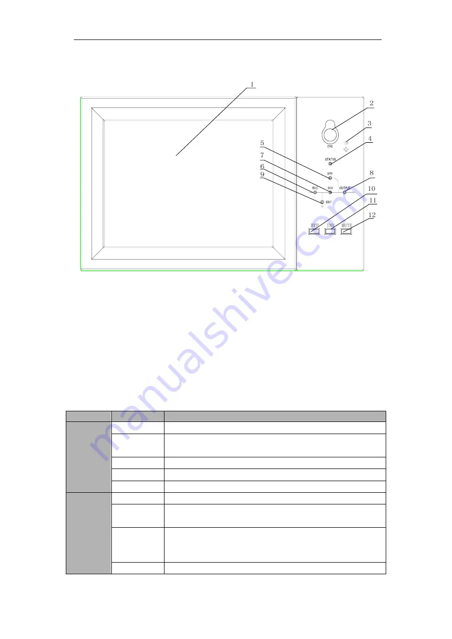
The structure of operator control and display panel for cabinet is shown in Fig.4-3.
1: LCD touch screen 2: EPO switch 3: Audible Alarm (Buzzer)
4: Status indicator 5: Bypass indicator 6: Rectifier indicator
7: Inverter indicator 8: Load indicator 9: Battery indicator
10: Bypass transfer 11: Inverter transfer 12: Mute
Fig.4-3 Control and display panel for cabinet
The LCD panel for cabinet is divided into three functional areas
:
LED indicator
,
control and operation keys and LCD touch screen.
4.3.1 LED Indicator
There are 6 LEDs on the panel to indicate the operating status and fault. (See Fig. 4-3).
The description of indicators is shown in Table 4.3
Table 4.3 Status description of indicator
Indicator
State
Description
Rectifier
indicator
Steady green Rectifier normal for all modules
Flashing
green
Rectifier normal for at least one module, mains normal
Steady red
Rectifier fault
Flashing red
Mains abnormal for at least one module
Off Rectifier
not
operating
Battery
indicator
Steady green Battery charging
Flashing
green
Battery discharging
Steady red
Battery abnormal (battery failure, no battery or battery reversed)
or battery converter abnormal (failure, over current or over
temperature) , EOD
Flashing red
Battery low voltage


