


Bringing the Benefits of Real-Time Data Collection to the World
Sutron Corporation, Tel: 703-406-2800,
http://www.sutron.com
37
needed for 60 samples. The unit must collect over half of the samples before the average will be
marked with a “G” as good.
MEASUREMENTS PER LOG:
Allows extra measurements to be taken which are not all
logged. For instance, a value of 4 with a 00:15:00 interval would cause the 9210 to measure
every 15 minutes, but log the specified sensor only every hour.
ENABLE:
This button is a quick way to disable a measurement if there’s a temporary issue that
doesn’t warrant completely deleting it.
LOG ID:
When this field contains a string, all sensors associated with this measurement are
logged as a group, with the Log ID used as the data set’s name. When the Log ID field is empty,
all items are logged separately, each with it’s own time stamp, units, and quality data. NOTE:
The maximum size of a log entry is 2048 bytes. Hence, be careful to not create a Log ID that
results in an entry larger than that. Also note that only 256 bytes of data can be shown for each
log entry on the Log tab. Of course, all 2048 bytes are included in an export of the log.
After creating or editing a measurement schedule, it’s tree entry is shown collapsed. Expand the
entry by clicking the "+" plus sign. This will show all the sensors assigned to the schedule. The
order in which the sensors appear is important, as it determines the order in which the sensors are
measured and logged.
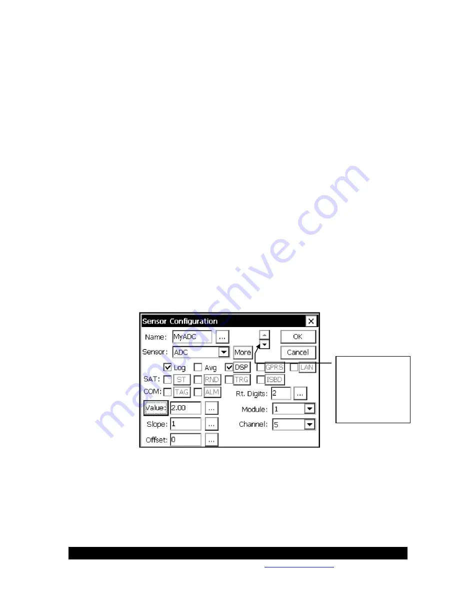
Sensor Configuration
A new sensor is added to a measurement schedule by selecting “[New Sensor]” and pressing
“Edit”. To edit an existing sensor, select the entry and press “Edit”. To delete a sensor, select it
and press “Delete”. When creating or editing a sensor, the following dialog is shown:
NAME:
The name used when logging (except when Log ID is active), and when displaying the
sensor value (in the EzSetup menu and the Sensors Tab).
SENSOR:
Defines the sensor type to measure. Click the box to see the list of all possible sensor
types. Note that each of these sensor types correspond to a sensor block that can also be used in
the graphical setup. This means that all the descriptions for sensor blocks in Appendix A apply to
the sensor type you select here.
Use these arrows
to move quickly
between all
sensors assigned
to the current
measurement
schedule.
Summary of Contents for Xpert2
Page 2: ......
Page 11: ...Chapter 1 Introduction...
Page 16: ......
Page 17: ...Chapter 2 Getting Started...
Page 86: ......
Page 87: ...Chapter 4 Graphical Setup Diagrams...
Page 104: ......
Page 105: ...CHAPTER 5 EXAMPLE SETUPS...
Page 128: ......
Page 129: ......
Page 130: ......
Page 131: ...Chapter 7 Installation...
Page 140: ......
Page 141: ...Chapter 8 Maintenance and Troubleshooting...
Page 145: ...Appendix A Setup Blocks...
Page 266: ......
Page 267: ...Appendix B Updating the Firmware...
Page 290: ......
Page 291: ...Appendix E Software Development Kit SDK...
Page 293: ...Appendix F Creating Custom Voice Files...
Page 330: ......


