


Bringing the Benefits of Real-Time Data Collection to the World
Sutron Corporation, Tel: 703-406-2800,
http://www.sutron.com
98
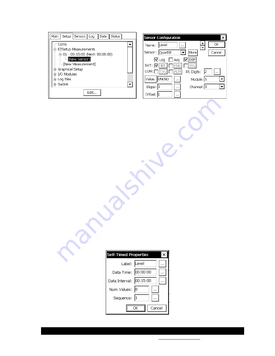
For this example, select a name (Level) select the sensor as a QuadSE, notice the Log and DSP
(display on LCD) are already checked, check the ST to send this sensor in a Self Timed
transmission, leave default of 2 right digits. Since digital channel one on the built-in 9210 digital
module cannot be used with a Quadrature shaft encoder, change the channel to 3 to have a setup
that is also 9210 compatible (Note: If an external 8080-0002 were used with the 9210, then
channel 1 would be valid).
Click the MORE button to get to the details of the QuadSE properties. See Appendix A to see all
the options available for this built-in sensor block. For this setup, leave the defaults.
Click the DSP button to see the properties for the display. It is possible to log a different amount
of precision than is displayed on the front panel; the default value used here comes from the Rt.
Digits set on the main Sensor Configuration page. For this setup, leave the defaults.
Click the ST button to see the properties for the self-timed transmission. Notice that all the fields
are filled in with details previously entered. These details include the Label (From Sensor
Configuration), Data Time/Interval (From the EZSetup Measurement schedule), Num Values
(From the Self Timed tree under Satlink) and an auto-numbering Sequence (This is the first
sensor configured, so it is 1).
Since the transmit format was previously left at the default of SHEF, the Num Values for this
sensor are configured here, it is possible to send a different amount of values per sensor. Had
BIN-INT (binary interleaved) been selected, this field would display the Num Values set in the
Self Timed setup under Satlink tree, but will not allow it to be changed from this properties page.
For this setup, leave the defaults.
Summary of Contents for Xpert2
Page 2: ......
Page 11: ...Chapter 1 Introduction...
Page 16: ......
Page 17: ...Chapter 2 Getting Started...
Page 86: ......
Page 87: ...Chapter 4 Graphical Setup Diagrams...
Page 104: ......
Page 105: ...CHAPTER 5 EXAMPLE SETUPS...
Page 128: ......
Page 129: ......
Page 130: ......
Page 131: ...Chapter 7 Installation...
Page 140: ......
Page 141: ...Chapter 8 Maintenance and Troubleshooting...
Page 145: ...Appendix A Setup Blocks...
Page 266: ......
Page 267: ...Appendix B Updating the Firmware...
Page 290: ......
Page 291: ...Appendix E Software Development Kit SDK...
Page 293: ...Appendix F Creating Custom Voice Files...
Page 330: ......


