


Bringing the Benefits of Real-Time Data Collection to the World
Sutron Corporation, Tel: 703-406-2800,
http://www.sutron.com
41
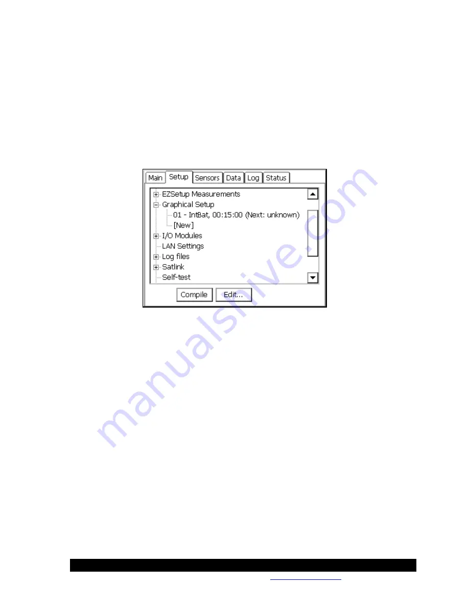
Graphical Setup
The
Graphical Setup
branch of the Setup tab is used to manage the portion of the system’s setup
that has been defined by interconnecting graphical blocks, where each block represents a
function such as sensor, measure, or log. This method of setup should be used to define sensors
that can't be setup using the
EZSetup Measurements
. This would include sensors that need to
have a polynomial, interpolation table or any other special processing done to them.
See the section in Appendix A that covers Processing blocks to see all the available processing.
See Chapter 4: Setup Diagrams, for detailed descriptions of how to set up sensors in this way.
This is also where setups defined with versions before 2.0.0.0 will be loaded.
The details of whatever measurements have been graphically defined will be displayed
underneath the
Graphical Setup
main branch. Some of the details shown for each measurement
include: sensor name, channel usage, last data value and quality (quality only if it is bad), and
scheduling information, including the time of the next measurement.
Selecting a measurement sub-branch and pressing
Edit
will cause the system to display the
measurement graphically, i.e., in terms of the blocks that define it. Only the blocks of the
measurement selected will be displayed.
Press the
View
button to view the block diagram in read-only mode.
To display the blocks of all measurements that have been defined graphically, select the
Graphical Setup
branch and press
Edit
.
To define a new measurement graphically, select [New] and press Edit. This causes the system to
display the graphical setup page with no blocks yet defined.
To remove an entire graphical block chain, click it, click EDIT and then click the left most block
and do a delete right
I/O Modules
The I/O modules branch displays the I/O modules currently connected to the system. These
modules are used for hooking up all sensors to the system except SDI-12 sensors. Up to ten
Summary of Contents for Xpert2
Page 2: ......
Page 11: ...Chapter 1 Introduction...
Page 16: ......
Page 17: ...Chapter 2 Getting Started...
Page 86: ......
Page 87: ...Chapter 4 Graphical Setup Diagrams...
Page 104: ......
Page 105: ...CHAPTER 5 EXAMPLE SETUPS...
Page 128: ......
Page 129: ......
Page 130: ......
Page 131: ...Chapter 7 Installation...
Page 140: ......
Page 141: ...Chapter 8 Maintenance and Troubleshooting...
Page 145: ...Appendix A Setup Blocks...
Page 266: ......
Page 267: ...Appendix B Updating the Firmware...
Page 290: ......
Page 291: ...Appendix E Software Development Kit SDK...
Page 293: ...Appendix F Creating Custom Voice Files...
Page 330: ......


