


Chapter 3: System Interface
3-1
Chapter 3
System Interface
3-1 Overview
There are several LEDs on the control panel and one on each Serial ATA drive
carrier to keep you constantly informed of the overall status of the system as well
as the activity and health of specifi c components. There are also two buttons on
the chassis control panel. This chapter explains the meanings of all LED indicators
and any appropriate response you may need to take.
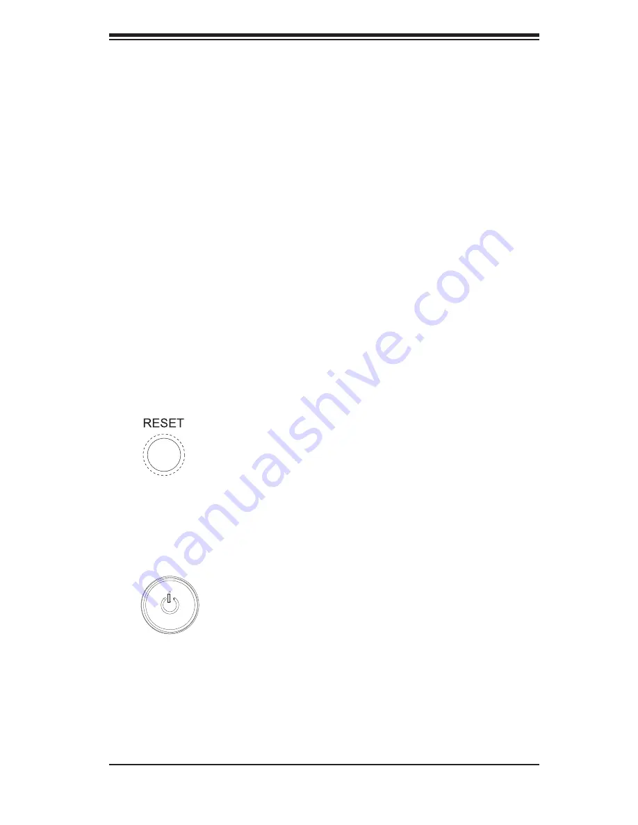
3-2 Control Panel Buttons
There are two push-buttons located on the front of the chassis. These are (in order
from left to right) a reset button and a power on/off button.
RESET
The reset button reboots the system.
POWER
This is the main power button, which is used to apply or turn off the main system
power. Turning off system power with this button removes the main power but keeps
standby power supplied to the system.
Summary of Contents for SuperWorkstation 5036T-T
Page 1: ...SUPER SuperWorkstation 5036T T USER S MANUAL Revision 1 0a...
Page 5: ...v Preface Notes...
Page 10: ...Notes x SuperWorkstation 5036T T User s Manual...
Page 16: ...1 6 SuperWorkstation 5036T T User s Manual Notes...
Page 19: ...Chapter 2 System Setup 2 3 Figure 2 1 Accessing the Inside of the 5036T T...
Page 24: ...3 4 SUPERWORKSTATION 5036T T User s Manual Notes...
Page 60: ...6 8 SUPERWORKSTATION 5036T T Manual Figure 6 5 Removing a SATA Drive Carrier...
Page 88: ...7 24 SuperWorkstation 5036T T User s Manual Notes...
Page 90: ...A 2 SuperWorkstation 5036T T User s Manual Notes...
Page 94: ...B 4 SuperWorkstation 5036T T User s Manual Notes...


