background image


119 

5.01.2 Editing a Trace 


Occasionally you may find a need to edit the tracing/contour cut created. This section presents two 
examples. 


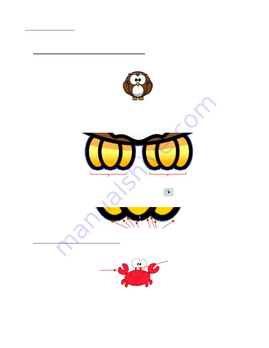
Contour cut doesn’t fit the original graphic in certain spots 


In the following example, the 

Cartoon Owl

 image will be used: 


During the process of tracing, it was found that 

the bottoms of the owl’s feet weren’t rounded like in the 

original image. Even trying different adjustments to 

Smoothing 

didn’t result in the desired fit. Note that 

a slight inline was applied to improve the accuracy of the fit but the bottom of the feet still need 
tweaking: 


With the trace line selected, click on the 

Node Edit Tools

 icon 

 and the nodes making up the path 

of the cut will appear.  Drag nodes, as needed, so that curves are formed: 


Contour cut contains paths you want deleted 


In the following example, a crab cartoon from 

Doodle Dragon Studios

 is traced: 


The issue in this example is that the space below the eyes should be cut out but not other internal 
shapes, such as the pupils of the eyes. Note the difference in what will be cut between marking and not 
marking the 

Keep Holes

 option in the 

Create Cut-Contour

 window: 

Trace line is flat along the bottom of owl’s feet 


Drag nodes to create curves 


An outside trace is 
needed 

Also needed is a trace of 
this area between the eyes 
and the body 

Summary of Contents for Skycut Series C with SignMaster

Page 1: ...anting to perform print and cut applications Chapter 4 covers using the Skycut accessory tools Chapter 5 covers several SignMaster functions of interest creating contour cuts and engraving fills It s...

Page 2: ...Wireless Stand Alone 21 1 12 4 USB Flash Drive 23 1 13 TEST DRAW SHAPES 27 1 14 DEFAULT SETTINGS TO CONSIDER 34 1 14 1 Advanced Settings 35 1 14 2 General Settings 37 1 14 3 Sys Information 39 1 15 MA...

Page 3: ...CEDURE 81 3 03 1 What You Need for Calibrating 81 3 03 2 Calibration Process 81 3 04 PERFORMING A PNC IN SIGNMASTER 84 3 04 1 Summary of Steps 84 3 04 2 Step by Step Simple PNC Project 85 3 05 PREPARI...

Page 4: ...01 2 Editing a Trace 119 5 02 ADDING A CONTOUR CUT TO A VECTOR IMAGE 121 5 03 ENGRAVING FILL 123 5 03 1 Engraving File Module and Settings 123 5 03 2 Inside Fills Versus Outside Fills 126 APPENDIX A T...

Page 5: ...tion If you continue to have technical questions or issues please contact your dealer as soon as possible If anything is missing from your order or you have mechanical issues with your Skycut please c...

Page 6: ...r appears to be defective your dealer should be notified as soon as possible For additional information regarding your warranty please refer to your Skycut dealer It is recommended that you retain the...

Page 7: ...er your box should also contain the following items Description Image Quantity 1 Power Supply 1 2 Power Cable 1 3 USB Cable 1 4 60 Blade blue cap 1 5 45 Blade red cap 2 6 Blade Holder 1 7 Test Pen and...

Page 8: ...Wheels 3 on 16 model 4 on 24 model grip the mat or material so that the grit shafts beneath will feed the mat or material in and out during cutting Power Button turns cutter on or off Ruler for measur...

Page 9: ...r cutting thinner materials such as paper all cardstock types heat transfer vinyl and wall auto decal vinyl The 600 blue capped blade is a much longer blade and is well suited for cutting thicker mate...

Page 10: ...ll if at all Having the blade fully extended will never result in better cutting In fact it can cause skewing tearing of the material damage to the blade and damage to the mat A good way to test your...

Page 11: ...cky side should now be dry enough for immediate use Test by making sure the mat will stick to your hand While washing with soap and water should revive the original adhesive you can add more adhesive...

Page 12: ...l not be required and you do not want the black levers down during extensive periods of cutting as it can damage the pinch wheels themselves Note that for a pinch wheel to grip properly it must be pos...

Page 13: ...reen 1 10 1 Set Screen Pressing the Set icon opens the Set Screen which contains access to many functions and settings Note the general description and section number if you wish to learn more about t...

Page 14: ...enough free room in both the front and the back for the mat to extend during cutting Powering On Connect the power cord to the power adaptor Plug the power cord into a wall outlet or power strip Then...

Page 15: ...o the Skycut Skycut can be located anywhere within range of the computer Other computers can cut to the Skycut Skycut can be located anywhere Cons Skycut is physically connected to the computer Cannot...

Page 16: ...ext Connect the USB cable to the right side of the cutter and into an available USB port on your computer Power on the Skycut and wait about 20 seconds The following window should open without the nee...

Page 17: ...rom the router the Skycut can be located What you ll need Name of your home office network The password for your network Carefully complete the following steps 1 On the Skycut s control panel select S...

Page 18: ...Then you would only need to tap on stu once to enter the letter s To enter numbers click on 123 to open the number entry screen For punctuation click on to open the extra characters screen To enter up...

Page 19: ...sword you entered If you are unable to successfully connect and the Skycut is within a few feet of your router please check your router s user manual and or search online for issues with your particul...

Page 20: ...ut control panel Click on Test A Port OK message should pop up Click on OK and then click on Apply The IP Address should now appear in the Vinyl Spooler window Should read SKYCUT C16 Select Windows Po...

Page 21: ...has previously been connected to a wireless network A The Skycut has never been set up wirelessly to a network Power on the Skycut and wait for the light to come on On your computer open your list of...

Page 22: ...A Port OK message should pop up Click on OK and then click on Apply The IP Address should now appear in the Vinyl Spooler window Click on Done and proceed to Section 1 13 Remember that your computer...

Page 23: ...ash Drive connection you will normally follow the steps presented in this section If you are new to SignMaster and or to your Skycut it is recommended that you go to Section 1 13 now and set up a file...

Page 24: ...ut Plot Engrave Tools icon 6th from the left on the upper middle task bar and this time select Send to Cutter The following window opens More about the settings on the left side of the window will be...

Page 25: ...o locate the USB flash drive you plan to use and name your PLT file After saving the file you can close the Vinyl Spooler window Insert the flash drive into the right side of the Skycut On the control...

Page 26: ...n the right to see more files 2 Once you have located the PLT file you want to cut double tap the name You will be taken back to the USB screen and the selected file name will be displayed Drag here t...

Page 27: ...o some testing with the pen tool But note that the following steps are for DRAWING not cutting Before inserting the blade holder into your cutter please read the following Sections 1 07 2 1 07 3 2 01...

Page 28: ...t of the Skycut such as the ruler to align the mat so that it s straight Lift the pinch lever to drop the pinch wheels onto the cutting mat Most of the mat and the paper should now be behind the cutte...

Page 29: ...ect the Arrow option Press and hold the left mouse button and drag the mouse in the Drawing Area to create the arrow shape In this test it doesn t matter where you place the arrow on SignMaster s Draw...

Page 30: ...and select Send to Cutter The following window opens More about the settings on the left side of the window will be covered in Section 2 03 For now just note where the shape will cut relative to the...

Page 31: ...re about this setting is covered in Section 2 03 3 Next the preset for drawing with the test pen will be selected Click on the down arrow to the right of Preset Condition In the drop down menu select...

Page 32: ...and a confirmation window opens where you have one more chance to note the Force and Speed at which the material will be cut Answer Yes to proceed No to cancel After selecting Yes the Skycut will draw...

Page 33: ...e Rotate option You will see the arrow rotate in the Preview Cutting with this setting results in the arrow pointing downwards as shown in the prior preview window Feed the mat this direction into the...

Page 34: ...es will cut 1 14 Default Settings To Consider The Skycut s control panel offers a number of default settings Some of these may not be important at this point in the learning process So you may want to...

Page 35: ...the Main Screen displays movement and location output based on the position of the cutting head Display X Y location of cutting head Option to use laser engraver Set up rows columns of repeats Turn on...

Page 36: ...e to cut or when moving from one cut shape to begin cutting another When turned off Up Speed will match the SPEED set for cutting Turning on this setting will change the Speed Force screen to display...

Page 37: ...l forward Pressing a DOWN arrow will move material towards the back of the cutter Pressing an UP arrow will move the material towards the back of the cutter Pressing a DOWN arrow will move material fo...

Page 38: ...r white light mode Screen and alarm has three settings Screensaver time Set a black out time in minutes for the control panel Alarm after finish working When a job is complete have an alarm sound five...

Page 39: ...displays current version numbers If you ever need to reset your Skycut press and hold Default All until it turns red Then wait for the button to update to Success If you ever need to change which soft...

Page 40: ...ls Note Do not pour cleaner onto a grit shaft Instead dab some adhesive remover onto a lint free cloth and then use the damp cloth to clean the shafts You can also use tweezers to remove any material...

Page 41: ...uctions Adhesive Removers 1 to completely strip a cutting mat of adhesive 2 to disarm adhesive long enough to remove large scraps of material that will not peel off Lint free Cloth 1 for dusting off y...

Page 42: ...ng enough with the test pen and paper shapes are not cutting in the correct locations refer to Section 2 02 2 2 01 What You Need to Understand About Cutting 2 01 1 You Have To Make Mistakes The key to...

Page 43: ...d to be done before inserting the cutting mat However this does not optimize the cutting force on the Skycut The recommended method for getting the same height set from one cut to the next is to use a...

Page 44: ...erve where the internal shape cut To locate a ring click on the General Power Shapes icon on the left side Tool Panel and go to Basic Shapes Basic o When cutting intricate shapes use a small letter or...

Page 45: ...he Drawing Area Note that this file called Controlling What Cuts is shared in a zip file available here Option 1 If no shapes are pre selected then all shapes will be sent to cut However if you pre se...

Page 46: ...d Star Then the Preview will only have circles and the stars present Option 2 Mark shapes not to be cut on the Objects tab of the Page Thumbnail Viewer o To access the Objects tab slick on the small i...

Page 47: ...row On the Object tab it can then be set not to cut Click this blue arrow Click the Objects tab All of the shapes appear in a list Arrow is selected Arrow will not cut Click this icon to turn off cutt...

Page 48: ...the menu appear Also the color is selected at the top o Switching to blue changes the window accordingly Drop down menu of colors used in the project Mark the Separate by Color option Black is select...

Page 49: ...iangulation This is far more precise than Absolute position because it takes into account not only any misalignment of your printout in the cutter but also any errors in the printing Most printers do...

Page 50: ...Settings Library icon The Blade Settings Library window will open Click on the down arrow to the right of Description where you can access a drop down menu for the Blade Type The red lines and dimens...

Page 51: ...yl Spooler Cut Options tab Send to be Cut General Use this location when you need to assign different settings to different layers of your project For example let s say you wanted to use the embossing...

Page 52: ...In the Vinyl Spooler window click on the Cut Options tab and the cut settings are located in the lower section of that window These settings should be understood thoroughly as you will be adjusting th...

Page 53: ...tments in order to get a clean test cut before proceeding with your larger cut Dull blades will need more force than new blades thus anticipate increasing the force over the life of the blade When cut...

Page 54: ...stance from the center of the blade shaft to the tip of the blade A pen or engraving tool has an offset of 0 because the tip is centered with the center of the pen engraving tool shaft But a blade is...

Page 55: ...der will result in large shapes not quite closing In some cutting programs Overcut is not a separate setting but rather automatically calculated and applied based on the Blade Offset entered However i...

Page 56: ...in much cleaner weeding of the cut circles IMPORTANT In the current version of SignMaster Pro Passes does not work if Assign Tools by Color is activated Therefore if you have a project requiring separ...

Page 57: ...ar to the blade holder preset you can enter settings for a particular material For example let s say you cut Georgia Pacific 110 lb cardstock at a Force of 55 and a Speed of 8 Use the following steps...

Page 58: ...e Preset Mode menu with this new listing Click on Done to close the Vinyl Spooler window The new preset will also now be available in the Send to be Cut Cutter Control window in the Preset Condition m...

Page 59: ...be saved on the Skycut control panel To create a preset Press the Force Speed icon to open the Force Speed screen Make the necessary changes to the SPEED and FORCE settings Select Save and the follow...

Page 60: ...tion 1 12 2 Note that there is a 15 character limit Click on OK when done You will now see the name of your new preset and you can press Save to add it to the saved presets with the FORCE and SPEED yo...

Page 61: ...located in relation to the material so that the shapes will cut in the appropriate location IMPORTANT The C16 Skycut has a maximum cutting width of 16 inches If you move the head too far to the left...

Page 62: ...f your material the intersection of grid lines on the mat etc If you do choose the latter make sure there s a way to clearly distinguish which intersection you want to use 3 On the Skycut s Main Scree...

Page 63: ...ashed should be close to the origin target Press X3 to zoom in 7 Use the arrow buttons to move the red as close as possible to the center of the origin target 8 Press OK At this point the blue dashed...

Page 64: ...reference 2 06 1 Advance Mode The Advance After Plot option in SignMaster Pro is actually controlled on the Skycut itself The function can be opened by going to Set Advance Mode on the control panel t...

Page 65: ...on layer is not penetrated by the blade Cutting vinyl to be applied to the inside of a car or home window but primarily viewed from outside of the window When cutting certain non homogenous paper mate...

Page 66: ...ding tool Speed Weed Text Only Mark this option when your design has a combination of both text and other shapes so that only the text will have Speed Weed applied Change offset here Click Settings ta...

Page 67: ...font used or alter the spacing of the letters etc without applying Undo Therefore the Weld Text option allows you to cut the text as if the Weld function has been applied 2 07 Important Checklist Bef...

Page 68: ...t perhaps just slightly smaller or larger in either or both dimensions Now this might be perfectly acceptable for the type of cutting you do Therefore it may not even be necessary to do this particula...

Page 69: ...0 mm Note that in the current version of SignMaster the display in this window is always in inches However you can enter values in mm by typing in mm after the number as shown Press the tab key and th...

Page 70: ...ave the shape drawn Using a mm ruler carefully measure the Width left to right and the Length top to bottom that drew Write these measurements onto your sheet These values can now be entered into the...

Page 71: ...wing at the correct size the calibration process is complete 2 08 2 Scale Calibration Using Inches for Measurement SignMaster has a built in resolution routine which can be used to easily perform this...

Page 72: ...ings for drawing and click on Cut Test to have the shape drawn Using a ruler carefully measure the Width left to right and the Height top to bottom that drew Write these measurements onto your sheet W...

Page 73: ...t to Apply Scale Adjustment Click on Yes and you ll be back in the Vinyl Spooler window To verify the scaling again click on Cutter Scale and repeat the same steps Make sure you leave your new scale f...

Page 74: ...ines Retract the blade 1 8 1 4 turn Return to 1 Try one or more of the following Decrease the force Make sure the mat is clean and sticky Try a different blade in case current one is chipped Dry the m...

Page 75: ...10 Settings Form for Cutting Materials Material Type Material Brand or Source Blade Force Speed Blade Offset Passes Ht Other Comments Number of Post It notes used to set blade tip distance above mate...

Page 76: ...kmar 0 05 1 2 mm B 1 25 5 250 10 Cardstock AC Textured 216gsm 80lb cover R 1 60 8 400 20 Alt 2 passes at Force 50 Cardstock Bazzill Linen R 1 55 8 400 20 Cardstock Carolina C2S Digital 144lb 234gsm R...

Page 77: ...icky mat Fabric Cotton Batik with Lite Steam A Seam 2 Y 1 65 5 250 20 Steam a Seam2 fused to wrong side paper removed and sticky side pressed down to mat Fabric Cotton Flannel with Lite Steam A Seam 2...

Page 78: ...rocery store 0 013 0 33mm R 1 70 6 300 20 Alt 2 passes at Force 60 Rhinestone Flock Sticky Flock R 2 45 8 400 20 Backing peeled and sticky side pressed to mat Rhinestone Rubber Hartco 425S green R 2 6...

Page 79: ...l Permanent Expressions Vinyl 51 Series Black R 1 20 8 400 20 Cut on mat Vinyl Wall no mat Vinyl Oracal 631 yellow R 1 20 8 400 20 Not using a mat note lower Blade Height Vinyl Wall no mat Vinyl Oraca...

Page 80: ...2 3 01 What Is a Print and Cut PNC The print and cut process also called PNC and contour cutting involves printing an image from SignMaster to any printer you own and then with the aid of the Skycut...

Page 81: ...takes a photo and displays it on the control panel along with a red and a large blue dashed 2 Aligning the red with the center of the test shape display several times until the blue dashed is centered...

Page 82: ...panel If you cannot see the test shape clearly press the LED button once so that it reads LED 50 and press the Get PIC button You should see three items in the photo the test shape that was drawn wit...

Page 83: ...on appears 10 Use the arrows keys to move the center of the red to the center of the test shape Photo of drawn test shape Red Blue dashed Red is now much closer to the middle of the test shape Blue da...

Page 84: ...clude the following o An imported raster image such as a JPG or PNG or BMP file o A vector image either imported or designed in SignMaster that will be printed but not cut o Text that will printed but...

Page 85: ...those dimensions 2 To change the Drawing Area click on the down arrow to open a drop down menu with many page options or just enter the dimensions directly 3 For a sample project go to this link and d...

Page 86: ...the right when this option is selected Print as PDF Select this option to send the file to Adobe Reader to then print to your printer Save as Image Select this option to export your printout as a JPG...

Page 87: ...intout directly if a cutting mat isn t required Note that in SignMaster a print and cut project is loaded upside down as shown in the following screenshot On the printout is a small arrow which is a r...

Page 88: ...orce and Speeds accordingly or select a Preset Otherwise if using the cut settings on the Skycut control panel turn these off Click on Done after making any changes 12 Back in the Contour Cutting Wiza...

Page 89: ...he Contour Cut Wizard window by clicking on Build Contours o Using Build Contours essentially takes you to the same Create Cut Contour window and the process is the same as presented in Section 5 01 T...

Page 90: ...r measurement After performing the print and cut use a mm ruler to measure how far away the cut lines are from the printed lines If you used an arrow focus only on the horizontal and vertical lines no...

Page 91: ...ed in the Create Cut Contour window Another possibility is that the contour cut line was inadvertently shifted from the graphic to be printed So check to see if a misalignment may have occurred when y...

Page 92: ...Copies option and the Quantity settings will appear below that 4 As you enter repeats the Preview will update showing the copies and the overall project dimensions If you need to size the project for...

Page 93: ...ow far the registration marks are located from the printed shapes More about this option and the Mark Options tab are covered in Section 3 08 Reduce the size of the original by returning to the main w...

Page 94: ...s option as a default or if you want to reduce the maximum spacing allowed between marks thus increasing the number of marks For example if Vertical Mark Spacing is lowered to 100 mm in this particula...

Page 95: ...rks from the image However you also need to make sure marks are not too close to anything printed so that the camera doesn t incorrectly attempt to scan the image instead of a registration mark Change...

Page 96: ...more flexibility when working with multiple registration marks such as being able to only scan one mark when there are repeats This is covered in Section 3 09 2 3 09 PNC from USB Flash Drive 3 09 1 P...

Page 97: ...tes the design should be facing downwards Click on Next and the following window will open where you can save the job as a PLT file on a USB flash drive inserted into a port on your computer Select Co...

Page 98: ...ra With Align selected press Set and the following window will open Verify that AutoMark box is checked Then click on Home Insert the flash drive into the right side of the Skycut and use the instruct...

Page 99: ...s the scanning of additional registration marks as repeats are cut This is far more accurate than only scanning the original four marks on significantly large projects The Array Mark window on the con...

Page 100: ...hree shapes cut 3 Single mark by purple arrow scanned next three shapes cut etc Alternate between scanning all 4 marks and scanning only 1 mark based on a set Interval Combination of 4 Mark and 1 Mark...

Page 101: ...utting thicker materials because the higher force applied by the blade can cause more drag on the material or cutting mat Use 1 Mark in situations where the material is thin the cuts are simple and th...

Page 102: ...pe to the next Thus use the same 20 Post It note method as with the blade holder Make sure your shapes will not be drawn where any of the pinch wheels travel over the material Otherwise the ink might...

Page 103: ...r each layer now need to be assigned If settings have already been entered and saved as Presets you only need to select from the Preset menu If you need to enter new settings which will be done for th...

Page 104: ...ing on Apply you will see that both colors now have settings assigned Because the blue layer is still selected its settings show along the bottom Load the material into the Skycut Click on Cut Now and...

Page 105: ...immediately open As soon as the drawing process has ended load the blade holder into the Skycut and proceed with the contour cut by clicking on OK in the prior window Once completed click on Done to...

Page 106: ...ecially works well on pop up cards Make sure you do some tests first to get the best settings for the scoring or embossing you need For scoring cardstock this typically involves a higher force 160 and...

Page 107: ...nce that layer should always be executed first In the Send to be Cut window check Absolute position and verify that Assign Tools by Color is not marked Click on the Cutter Control tab and enter approp...

Page 108: ...0 25 mm These tiny offset lines will then produce a slightly thicker overall outline of your shapes This works better than line filled embossing which can stress the cardstock and cause wrinkling Her...

Page 109: ...t such as metal tags trophy plates charms etc it s very important to have precise alignment before proceeding Therefore the camera on the Skycut will be used to set the origin for engraving If you hav...

Page 110: ...h both the heart and the design selected drag to the lower right corner until it snaps to the right and bottom sides of the Page Drawing Area Note to better illustrate placement on the page and later...

Page 111: ...de of the tag with a vertical grid line and the bottommost side of the tag with a horizontal grid line The intersection of the two gridlines will be the origin for the engraving process Double sided t...

Page 112: ...ding the tag Then use the camera instructions in Section 2 05 1 to set the origin even more precisely by getting the blue dashed in the middle of the grid intersection After clicking on Home press dow...

Page 113: ...113 4 04 Settings Form for Accessory Tools Application Material Tool Force Speed Cut Up Passes Surface Other Comments 2009 2018 Sandy McCauley All Rights Reserved...

Page 114: ...of 0 004 0 1 mm Engraving Aluminum 36 gauge Scratch Engraver 1 20 11 550 15 mat Used a Line Fill of 0 004 0 1 mm Engraving Copper 36 gauge Scratch Engraver 1 30 11 550 15 mat Used a Line Fill of 0 004...

Page 115: ...aced This is done through a process called vectorization 5 01 1 Step by Step Tracing Process The following steps are a sample tutorial using the Create Contour Cut feature in SignMaster 1 For this pro...

Page 116: ...city setting at the top If the fit isn t tight enough decrease the Smoothing setting After making changes click Retrace to return to the original tracing window and then click on Trace again Click her...

Page 117: ...king on the Original tab at the bottom Click on Trace to apply the new settings 9 After clicking on Apply a new group of settings appear giving you additional options such as Whether the cut line is c...

Page 118: ...ive number normally very small to cut slightly inside the printed image 10 Click on Accept after making any changes and you will be returned to the Drawing Area If you click on the Objects tab on the...

Page 119: ...he feet still need tweaking With the trace line selected click on the Node Edit Tools icon and the nodes making up the path of the cut will appear Drag nodes as needed so that curves are formed Contou...

Page 120: ...ing Area Select the contour and go to Curves Break Apart The individual paths will now be separate layers on the Objects tab and you can delete each one that is not needed Keep Holes not checked Area...

Page 121: ...our For example the following Batman SVG file is imported into Signmaster and then the Contour Cut Wizard window is opened Note that comparing the View Print only preview with the View Cut only previe...

Page 122: ...our cut increase Outline to the desired size and for an inline cut decrease Outline slightly so that it s a negative number Outline is set to 1 8 0 125 inches Inline is set to 1 32 0 03 inches After c...

Page 123: ...and Settings If you wish to fill in a shape with a line pattern SignMaster offers an Engraving Module which can be opened by clicking on the Plugins icon and selecting Engraving Module The following...

Page 124: ...sive inset pattern based on the original shape the tool drops to complete a path raises moves to the next path drops to complete that path etc Some shapes work better than others with an Island Fill T...

Page 125: ...ol For the Skycut engraver use 0 004 inches or 0 1 mm Tool Offset This setting is the distance between the engraving lines as a percentage of the Tool Diameter Lowering this setting will decrease the...

Page 126: ...ll with lines such as this If shapes are added around these stars then the fill pattern reverses to fill the space between the original shapes and the new outside shapes If another shape is added to t...

Page 127: ...located from your router In SignMaster s Vinyl Spooler window under the Connection tab make sure you have selected TCP and entered the same IP address you selected during setup on the Skycut s contro...

Page 128: ...nment error will become more pronounced with a long cut When you first drop the pinch wheels use the arrow keys to feed the vinyl for the length of the cut to make sure it is feeding straight If not t...

Page 129: ...will stop If the Skycut stops and the head is not located near the left side Make sure it s not a communication issue You may have exceeded a buffer limit Try reducing the number of nodes Select the...

Page 130: ...ing Try raising the blade holder in the blade holder seat If the blade is too close to the material not enough force is being applied Refer to Section 2 01 3 Set the Blade Height Above the Material Ma...

Page 131: ...to in SignMaster Perform the calibration procedure shown in Section 2 08 ____________________ My shapes are not completely cutting out They are still attached to the waste part of the material Make su...

Page 132: ...s be corrected by slowing the speed and making sure the cuts aren t so deep that the blade is causing some drag to occur An alternative solution is to add intermediate registration marks Refer to Sect...

Reviews: