6-1
C H A P T E R
6
Removing and Replacing Major
Subassemblies
This chapter describes how to remove and replace the major subassemblies.
This chapter contains the following topics:
■
Section 6.1 “Power Supply” on page 6-1
■
Section 6.2 “Cable Assemblies” on page 6-3
■
Section 6.3 “Speaker Assembly” on page 6-13
■
Section 6.4 “Fan Assembly” on page 6-16
6.1
Power Supply
To remove and replace the power supply, proceed as follows.
6.1.1
Removing the Power Supply
1. Power off the system, remove the system cover, and attach an antistatic wrist strap
as described in Chapter 5 “Preparing for Component Removal and Replacement.”
Caution –
Use proper ESD grounding techniques when handling components. Wear
an antistatic wrist strap and use an ESD-protected mat. Store ESD-sensitive
components in antistatic bags before placing them on any surface.
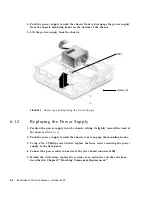
2. Disconnect the power cable connector from riser board connector J501 (
FIGURE 6-1
).
3. Using a No. 2 Phillips screwdriver, remove the three screws securing the power
supply to the back panel.
Summary of Contents for Sun Blade 100
Page 6: ...vi Sun Blade 1000 Service Manual September 2000...
Page 8: ...viii Sun Blade 100 Service Manual October 2000...
Page 26: ...xxvi Sun Blade 100 Service Manual October 2000...
Page 30: ...xxx Sun Blade 100 Service Manual October 2000...
Page 38: ...xxxviii Sun Blade 100 Service Manual October 2000...
Page 40: ...1 2 Sun Blade 100 Service Manual October 2000 FIGURE 1 1 Sun Blade 100 System...
Page 48: ...1 10 Sun Blade 100 Service Manual October 2000...
Page 52: ...2 4 Sun Blade 100 Service Manual October 2000...
Page 94: ...4 26 Sun Blade 100 Service Manual October 2000...
Page 102: ...5 8 Sun Blade 100 Service Manual October 2000...
Page 120: ...6 18 Sun Blade 100 Service Manual October 2000...
Page 154: ...8 22 Sun Blade 100 Service Manual October 2000...
Page 158: ...9 4 Sun Blade 100 Service Manual October 2000...
Page 162: ...10 8 Sun Blade 100 Service Manual October 2000...
Page 170: ...A 8 Sun Grover Service Manual October 2000...


