Page 11
Electronics
Induction Range (IR) Series
Induction Range (IR) Series
2-11
#827176 - Revision A.2 - September, 2017
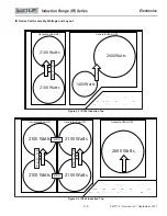
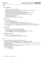
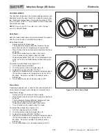
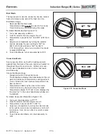
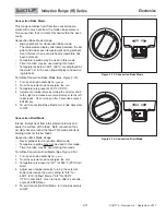
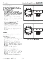
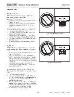
Figure 2-3. Coil Assembly Locations
f.
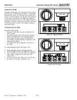
Error Code Indicator
Touch
“+”
pad during the Coil Temperature test.
•
Six
“.”
are displayed on left rear control zone.
•
Front control zone shows 0-8 dimmed
“.”
based on how many error codes are logged.
•
Fully lit LED indicates which error is being displayed in the 2-digit display.
•
If only a single error has been logged, only a single fully lit LED is displayed.
•
If no errors are logged
SIM/MLT
,
HI
, and
“.”
are not displayed and “- -” is displayed in the 2-digit display.
•
2-digit display shows the corresponding error code stored in memory.
•
Front left
SIM/MLT
and
HI
are dimmed. A touch of the front control zone
SIM/MLT
or
HI
pads cycles through
•
the stored error codes.
Touch and hold
TIMER
pad for 5 seconds to clear error code history.
•
Clearing the error code history is only possible if at least one error was logged.
•
Clearing the error code history is confirmed by a double beep.
•
If an error is currently present when the log is cleared, it immediately regenerates an error code.
•
“-”
pad engages the Coil Temperature test.
•
“+”
pad engages Showroom Mode menu.
•
g.
Showroom Mode
Touch
“+”
pad during the Error Code Indicator.
•
Seven
“.”
displayed on left rear control zone.
•
Touch the left front control zone
HI
pad to engage showroom mode.
•
SH
is displayed in the 2-digit display when in showroom mode.
•
Touch the left front control zone
SIM/MLT
pad to disengage showroom mode.
•
”-”
pad engages the Error Code indicator.
•
“+”
pad engages the Software Version indicator.
•
h.
Software Version Indicator
Touch
“+”
pad during Showroom Mode.
•
Eight
“.”
are displayed on left rear control zone.
•
2-digit display cycles to show the software version of the control.
•
“-”
pad engages the Showroom Mode menu.
•


