Page 10
Induction Range (IR) Series
Induction Range (IR) Series
Electronics
2-10
#827176 - Revision A.2 - September, 2017
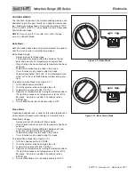
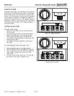
Control Temperature Readout
Touch
“+”
pad during Unit Reconfiguration.
•
Three
“.”
displayed on left rear control zone.
•
2-digit display shows the ambient control temperature in °C.
•
Over 99° C (210° F), the decimal point of the 2 digit display turns on to indicate the temperature is 100° C or
•
higher.
“-”
pad engages Unit Reconfiguration.
•
“+”
pad engages Heat Sink Temperature.
•
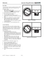
Heat Sink Temperature Test
Touch
“+”
pad during the Control Temperature Readout.
•
Four
“.”
displayed on left rear control zone.
•
2-digit display shows the current heat sink state.
•
State is temperature based and not the actual heat sink temperature.
•
“0”
– temperature is ≤ 176° F – cooktop works correctly.
•
“1”
– temperature is > 176° F – boost is disabled for affected zones.
•
“2”
– temperature is > 192° F and ≤ 201° F – affected zone limited to 60% power.
•
temperature is > 201° F and ≤ 210° F zones limited to 40% power.
•
“3”
– temperature is > 210° F – all affected zones turned off
•
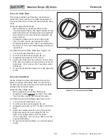
Heat Sink Performance
Front left control zone
SIM/MLT
and
HI
LEDS are on.
•
Touch the front left control zone
SIM/MLT
or
HI
pad cycles through the heat sink temperatures.
•
Left front control zone displays dimmed 1, 2, or 3
“.”
to indicate heat sink number, with one
‘.’
on to indi-
•
cate which heat sink temperature is displayed.
•
First LED is generator board #1.
•
Second LED is generator board #2.
•
Third LED is generator board #3.
A touch of the
“-”
pad engages the Control Temperature Readout.
•
A touch of the
“+”
pad engages the Coil Temperature test.
•
e.
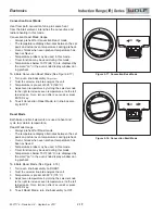
Coil Temperature Test
Touch
“+”
pad during the Heat Sink Temperature test.
•
Five
“.”
are displayed on left rear control zone.
•
2-digit display shows the coil temperature in °C.
•
Over 99° C (210° F), the decimal point of the 2 digit display turns on to indicate the temperature is 100° C
•
(210° F) or higher.
Front left
SIM/MLT
and
HI
are on. Touch the front left control zone
SIM/MLT
or
HI
pad cycles through the
•
coil temperatures.
Front left control zone displays dimmed 1, 2, 3, 4, or 5
“.”
to indicate coil number, with one
“.”
on to indicate
•
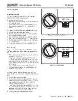
which coil temperature is displayed (See figure 2-3 for coil locations).
• First LED is coil assembly and NTC #1
• Second LED is coil assembly and NTC #2
• Third LED is coil assembly and NTC #3
• Fourth LED is coil assembly and NTC #4
• Fifth LED is coil assembly and NTC #5
“-”
pad engages the heat sink temperature test.
•
“+”
pad engages the error code indicator.
•
Coil Temperature Performance Impact
160° C (320° F) boost is disabled for affected zones.
•
240° C (464° F) affected zones are limited to 60% power.
•
260° C (500° F) affected zones are turned off.
•
285° C (545° F) all zones are turned off.
•


