background image


Global 400 User Manual 

38 of 85 

v1.1 revision 1 

Chapter 3: Configuring the unit 


2 February 2016 

This setting controls the IP address of the qualifier for Ethernet networks. 

Subnet Mask 

Default: 255.255.255.0 
This setting controls the subnet mask for Ethernet networks. 

Gateway 

Default: 192.168.1.113 
This setting controls the default gateway setting for Ethernet networks. 

Use DHCP 

Default: No 
This setting determines if the qualifier will attempt to automatically acquire a network address or 
if it will use the one entered manually.  When set to yes, the IP Address, Subnet Mask, and 
Gateway settings are ignored. 

Unit Setup 

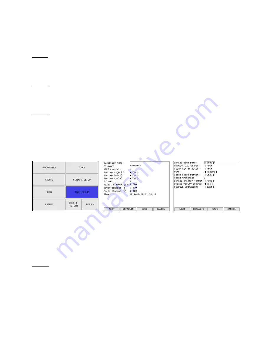
The Unit Setup screen contains the settings for the overall unit. 


Figure 40: Main menu – Unit Setup 


Figure 41: Unit Setup screen – page 1 


Figure 42: Unit Setup screen – page 2 

Function keys 

1.


NEXT – Goes to the other page of the unit setup screen. 

2.


DEFAULTS – Goes to the Reset Defaults screen 

3.


SAVE – Saves changes made to the qualifier configuration. 

4.


CANCEL [ESC] – Cancels changes made to the qualifier configuration. 

Page 1 

Qualifier Name 

The qualifier name can be up to 25 numbers, letters, or decimal points. 
The qualifier name is sent to the network in the Controller Name field of various commands. 

Summary of Contents for Global 400

Page 1: ...Global 400 User Manual v1 1 revision 1 2 February 2016 Manual Part Number 857412...

Page 2: ...Using the unit 12 Concepts 13 Run Screen 14 History 17 Unit Status 18 Rundown Graph 19 Network Status 19 Tool Status 20 I O State 21 Chapter 3 Configuring the unit 22 Introduction 23 Saving Configurat...

Page 3: ...n Options 53 Supported Commands 56 Unsupported Commands 57 Chapter 6 ToolsNet 59 Introduction 60 Configuration Options 60 Chapter 7 EtherNet IPTM 62 Vendor Specific Objects 63 Assembly Object Connecti...

Page 4: ...Global 400 User Manual 4 of 85 v1 1 revision 1 Quick Start 2 February 2016 Quick Start...

Page 5: ...series of quick beeps and the display should show the loading progress Once the loading is completed the unit should go to the Run screen If the unit stays on the loading screen with an error please...

Page 6: ...rections on screen to learn the tool Once the tool has found the unit you may need to perform an additional step for the unit to know which type of tool was just learned Holding tools air tools and ne...

Page 7: ...Tool If the just learned tool is a digital tool the default name will be the tool serial number Before you can run the tool you must first assign it to a parameter Return to the menu by pressing ESC...

Page 8: ...shown in black instead of white to indicate that it was set up successfully Press the button below SELECT to select Parameter 1 You will be returned to the Run screen now with Parameter 1 selected You...

Page 9: ...Global 400 User Manual 9 of 85 v1 1 revision 1 Chapter 1 Overview 2 February 2016 Chapter 1 Overview 2 February 2016 Chapter 1 Overview...

Page 10: ...force to any cable or fitting Cautions Please use caution when handling this or any other electrical appliance This unit accepts an AC input voltage from 100 240 VAC Trying to operate this unit with...

Page 11: ...sted through the user interface See the Unit Setup section in the next chapter The Global 400 has two RJ 45 Ethernet ports to allow it to be used in a chain or ring network configuration The USB A con...

Page 12: ...Global 400 User Manual 12 of 85 v1 1 revision 1 Chapter 2 Using the unit 2 February 2016 Chapter 2 Using the unit...

Page 13: ...ls before it can be run A parameter may additionally have a holding tool assigned Groups Groups are multiple parameters that must all run together and can run simultaneously in any order The Global 40...

Page 14: ...he area of the screen showing the current parameter and batch count for the tool will be shaded with a color indicating the status of the tightening Red A rejected tightening occurred Green An accepte...

Page 15: ...meter 5 Tool Status Indicator Shows the status of the tool for the parameter 6 Unit lock Indicates if the unit is locked and requires a password to access menu functions 7 Unit Radio Status Shows the...

Page 16: ...o Status Shows the status of the unit radio 9 Network Status Shows the status of the Ethernet and current number of connections 10 Function key 1 Shows the current function of function key 1 11 Functi...

Page 17: ...ndicator The unit radio status indicator shows the status of the radio in the unit In normal use the indicator should be green with no number If the radio is not working correctly the indicator will b...

Page 18: ...network commands Unit Status Figure 6 Unit Status screen Function keys 1 GRAPH When a single air tool is running goes to the Rundown Graph screen For other tool types or when a group is running this...

Page 19: ...nd vertical lines showing the timers purple for Timer Min and Timer Max blue for Timer Clutch Additionally the total time for the rundown is shown at the right end of the horizontal axis Network Statu...

Page 20: ...hows a color based on the quality of the signal Green The signal from this radio is strong and will work at best performance Yellow The signal from the radio is weaker than recommended for best perfor...

Page 21: ...vice this key will be blank 3 NEXT ENT Show the I O device with the next address When showing the last defined device this key will be blank 4 RETURN ESC Returns to the Unit Status Screen The I O Stat...

Page 22: ...Global 400 User Manual 22 of 85 v1 1 revision 1 Chapter 3 Configuring the unit 2 February 2016 Chapter 3 Configuring the unit...

Page 23: ...ime for the item Entering letters The unit has a special screen that allows using the numeric keypad to enter letters for fields that allow them such as a parameter name To get to this screen press EN...

Page 24: ...ithout changing the value Main Menu Figure 14 Main menu The Global 400 menu provides the entry point to configure and control the unit You must enter the box password before entering the menu from the...

Page 25: ...Empty slot selected Figure 20 Holding tool selected Function keys When a learned tool is highlighted the function keys are 1 REPLACE Learn a new tool in place of the current tool in this slot If you...

Page 26: ...he tool configuration Name The tool name can be up to 25 numbers letters or decimal points The tool name is shown on screen when running a parameter that uses the tool but is not reported to the netwo...

Page 27: ...at the end of the Next Calibration row and pressing the ENT key This can be helpful when the recalibration period is a full month because you will only need to update the month and year when at the en...

Page 28: ...he qualifier to no longer respond to the tool and will make any parameters using the tool and any groups or jobs using those parameters invalid Parameters Selecting Parameters Figure 25 Main menu Para...

Page 29: ...scards changes to the parameter and returns to the Choose Parameter screen Common Fields Name The parameter name can be up to 25 numbers letters or decimal points The parameter name is shown on screen...

Page 30: ...tion to a no active parameter state When set to no the qualifier will restart the parameter when a batch is completed This setting is ignored when running the parameter as part of a group or job Click...

Page 31: ...s of the Torque Min and Max as well as the torque reported with each tightening Torque Min Default 10 of tool capacity Range 0 to tool capacity This setting controls the minimum required torque for a...

Page 32: ...5 s This setting controls the maximum time the tool can run for a valid tightening Timer Pulse Range 0 to 65 5 s This setting controls the minimum time a tool needs to pulse if using a pulse tool algo...

Page 33: ...available for selectable groups 2 EDIT Edit the currently highlighted group 3 COPY Selects the currently highlighted group to be copied to another location 4 RETURN ESC Returns to the main menu The Ch...

Page 34: ...group when the group is completed When set to yes the qualifier will stop when the group completes and transition to a no active parameter state When set to no the qualifier will restart the group wh...

Page 35: ...Jobs Figure 34 Choose Job screen Function keys 1 SELECT ENT Select the currently highlighted job to run Only available for selectable job 2 EDIT Edit the currently highlighted job 3 COPY Selects the c...

Page 36: ...ob when the job is completed When set to yes the qualifier will stop when the job completes and transition to a no active parameter state When set to no the qualifier will restart the job when it comp...

Page 37: ...steps when running it as part of the group This column will be empty for group steps When a parameter is selected this column will be filled with the batch currently defined in the parameter itself Ch...

Page 38: ...se the one entered manually When set to yes the IP Address Subnet Mask and Gateway settings are ignored Unit Setup The Unit Setup screen contains the settings for the overall unit Figure 40 Main menu...

Page 39: ...e the new channel The radio frequencies used by each channel can be found in Chapter 10 Product Specifications Beep on reject Default yes This setting determines if the qualifier will sound the beeper...

Page 40: ...reen blue or yellow behind the parameter that received the result to complete a batch Cycle timeout Default 1 Range 0 to 10 seconds This setting controls how long the on screen indication of an accept...

Page 41: ...When set to yes the qualifier will clear the VIN when an operation completes regardless of if the operation is set to repeat When directly running a parameter the VIN will be cleared when a batch is c...

Page 42: ...ng the learn process Serial printer format Default None Values None Line CSV This setting determines the format used for serial printing of tightenings Bypass Verify Inputs Default no This setting det...

Page 43: ...If you only want to temporarily disable the password use the RETURN button as described on the Main menu screen to return to the run screen Reset Defaults Figure 44 Reset Defaults screen Function key...

Page 44: ...ter finishing the channel change for the rest of the tools Once a tool has been updated press NEXT to go to the next tool Once all tools have been tried or skipped press DONE to complete the channel c...

Page 45: ...y will be blank 4 RETURN ESC Returns to the Run Screen The Events screen shows the log of non tightening events that have occurred More information is available via the PC software application This sc...

Page 46: ...Global 400 User Manual 46 of 85 v1 1 revision 1 Chapter 4 Serial communications 2 February 2016 Chapter 4 Serial communications...

Page 47: ...further specifies a format of data within the bar code The data is grouped into sections separated by a percent symbol If the bar code data does not start and end with a percent symbol it will be trea...

Page 48: ...e command format As such the same VIN could be provided as VIN1234567 5 Start Job This command instructs the unit to select a job Any other running parameter group or job will be stopped before starti...

Page 49: ...ing a group with multiple parameters use command 30 Reset parameter batch count 11 Start Parameter This command instructs the unit to start a parameter Any other running parameter group or job will be...

Page 50: ...10 Reset batch count Serial Printer The Global 400 provides serial printer output in two formats line and CSV The Global 400 will print tightenings based on the format selected on the second page of t...

Page 51: ...Global 400 User Manual 51 of 85 v1 1 revision 1 Chapter 4 Serial communications 2 February 2016 Torque Status Angle Angle Min Angle Max Angle Status...

Page 52: ...Global 400 User Manual 52 of 85 v1 1 revision 1 Chapter 5 Atlas Copco Open Protocol 2 February 2016 Chapter 5 Atlas Copco Open Protocol...

Page 53: ...1 2 and 3 and jobs 10 11 and 12 are defined in the unit MID 0030 Job ID Upload request would return jobs 10 11 12 301 302 and 303 in the reply Similarly the MID 0034 Job Info subscription will give a...

Page 54: ...ain up to the specified number of retries If no response is received after all retries the ACOP connection is considered broken and will have to be re established This will terminate all subscriptions...

Page 55: ...nit operation or modify configuration When this setting is set to yes all supported commands listed below are handled When set to no the following MID commands will return an error 0018 Parameter Sele...

Page 56: ...unter 0030 0031 1 2 Job ID upload request reply 0032 0033 1 3 Job data upload request reply 0034 0037 1 4 Job info subscribe acknowledge unsubscribe 0038 1 2 Select Job 0039 1 2 Job restart 0040 0041...

Page 57: ...ightening result Station data 0107 Last PowerMACS tightening result Bold data 0108 Last PowerMACS tightening result data acknowledge 0109 Last PowerMACS tightening result data unsubscribe 0110 Display...

Page 58: ...otocol 2 February 2016 MID Revisions Command 0260 Tool tag ID request 0300 0301 Histogram upload request reply 0261 0264 Tool tag ID subscribe acknowledge unsubscribe 0400 0403 Automatic Manual mode s...

Page 59: ...Global 400 User Manual 59 of 85 v1 1 revision 1 Chapter 6 ToolsNet 2 February 2016 Chapter 6 ToolsNet...

Page 60: ...ork protocols supported by the qualifier ToolsNet requires the controller to establish connections Since the qualifier will repeatedly make network requests to attempt to establish a network connectio...

Page 61: ...fied number of retries If no response is received after all retries the ToolsNet connection is considered broken and will have to be re established Keep alive Default 30 seconds Range 0 to 3600 second...

Page 62: ...Global 400 User Manual 62 of 85 v1 1 revision 1 Chapter 7 EtherNet IPTM 2 February 2016 Chapter 7 EtherNet IPTM...

Page 63: ...vice The maximum number of tools as specified for the product Instance Attributes ID Access Name Data Type Description of Attribute Semantics of Value 1 Set Name SHORT_STRING Name of the tool displaye...

Page 64: ...ation Bit 1 Cycles Services Service Code Available in Service Name Description of Service Class Instance 0x05 No Yes Reset Resets the tool slot to factory defaults No actual action is taken with the t...

Page 65: ...ributes were modified 3 Set Tool UINT Instance number of tool used for this parameter 4 Set Holding Tool UINT Instance number of holding tool used for this parameter 5 Set Batch USINT Batch size 6 Get...

Page 66: ...torque must be steady before it is reported Measured in 0 1s 1 Only available for parameters using tools of type 2 click wrench 2 Only available for parameters using tools of type 3 digital torque wre...

Page 67: ...in the device The maximum number of groups as specified for the product Instance Attributes ID Access Name Data Type Description of Attribute Semantics of Value 1 Set Name SHORT_STRING Name of the gr...

Page 68: ...lue 1 Set Name SHORT_STRING Name of the tool displayed on screen Maximum length is 25 characters 2 Get Last Modified DT Last time the job attributes were modified 3 Get Number of Steps USINT Number of...

Page 69: ...ect Bit 2 Beep on cycle 4 Set Beeper Volume USINT Volume level of the beeper Range 0 10 0 disables the beeper 5 Set Batch Timeout ITIME Duration to show the batch indicator on screen If 0 the indicato...

Page 70: ...ributes ID Access Name Data Type Description of Attribute Semantics of Value 1 Set Require to start BOOL Indicates if a VIN is required to run an operation 2 Set Clear on complete BOOL Indicates if th...

Page 71: ...pe of item to run 0 Parameter 1 Group 2 Job Ignored if Item Number is 0 Batch Reset USINT When this value changes the batch counts of the currently running parameter or group is reset Suspend BOOL Whe...

Page 72: ...b Batch USINT Sets the batch size for the selected parameter If Item Type is not 0 Parameter this value is ignored If this value is 0 the parameter size stored in the Global 400 will be used Total siz...

Page 73: ...angle required for a tightening in the parameter VIN SHORT_STRING Max length 100 Total size 55 194 bytes 111 Name Data Type Description Tightening ID UDINT ID number of the last tightening Time DT Tim...

Page 74: ...oup provide a view of the current qualifier status and do not provide any information about tightenings 120 Name Data Type Description Parameters ARRAY of STRUCT of Status of up to 16 parameters curre...

Page 75: ...8 Name Data Type Description Parameter USINT Selects a parameter for the Global 400 to run May be any value in the ranges 0 7 0 7 A H see above for details Values outside these ranges will cause the...

Page 76: ...st parameter change Tightening Type CHAR Type of the last tightening One of B Good tightening that finished a batch C Good tightening that did not finish a batch R Bad tightening N No tightening perfo...

Page 77: ...values Total size 102 bytes 101 This connection point corresponds to the mask 1 of the EIP network card for the Global 8 Name Data Type Description Parameter CHAR A H Tightening Status CHAR Status of...

Page 78: ...the mask 2 of the EIP network card for the Global 8 Name Data Type Description Tightening status CHAR Status of the last tightening One of O Good tightening N Bad tightening or no tightening performe...

Page 79: ...Global 400 User Manual 79 of 85 v1 1 revision 1 Chapter 8 Data Management 2 February 2016 Chapter 8 Data Management...

Page 80: ...es Results The results file will be saved to the USB drive as res csv where the is the last four digits of the unit serial number This file contains all tightening results saved in the unit s memory i...

Page 81: ...Files Firmware Firmware files have the extension bec If a file is found the unit will validate the file before uploading it If a firmware file is uploaded the unit will reprogram itself with the new...

Page 82: ...Global 400 User Manual 82 of 85 v1 1 revision 1 Chapter 9 Firmware Updates 2 February 2016 Chapter 9 Firmware Updates...

Page 83: ...l seconds When the drive is detected you should see the USB menu If the unit does not detect the drive contact support If the update was emailed to you you may also try another USB drive 5 To upload t...

Page 84: ...Global 400 User Manual 84 of 85 v1 1 revision 1 Chapter 10 Product Specifications 2 February 2016 Chapter 10 Product Specifications...

Page 85: ...ver sensitivity 100 dBm 1 packet error FCC Part 15 247 OUR XBEEPRO Industry Canada 4214A XBEEPRO Europe CE ETSI FCC Statement Channel Frequencies Channel Frequency GHz 1 2 410 2 2 415 3 2 420 4 2 425...

Reviews: