36
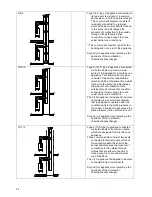
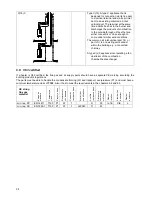
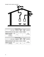
C(4)3
Type C4. A type C appliance connected via
its two ducts to a single or a common
duct system
1)
and for a natural draught.
This common duct system consists of
two ducts connected to a terminal,
which at the same time admits fresh air
to the burner and discharges the
products of combustion to the outside
through orifices that are either
concentric or close enough to come
under similar wind conditions.
1)
This common duct system is part of the
building and not a part of the appliance
A type C(x)3 appliance incorporating a fan
upstream of the combustion
chamber/heat exchanger.
C(10)3
Type C(10) “A type C appliance connected
via its two ducts to a common duct
system 13) designed for more than one
appliance. This common duct system
consists of two ducts connected to a
terminal, which at the same time admits
fresh air to the burner and discharges
the products of combustion to the
outside through orifices that are either
concentric or close enough to come
under similar wind conditions.
The C(10) appliance is designed to become
connected to a common duct system
that is designed to operate under the
conditions where the static pressure in
the common flue duct might exceed the
static pressure in the common air duct.”
A type C(x)3 appliance incorporating a fan
upstream of the combustion
chamber/heat exchanger.
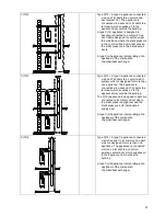
C(11)3
Type C(11)A type C appliance connected
via its two ducts to its common ducts
which are designed for more than one
appliance.
These common ducts consist of two ducts
connected to their terminals, which at
the same time admit fresh air to the
burner and discharge the products of
combustion to the outside through
orifices that are either concentric or
close enough to come under similar
wind conditions.
The C(11) appliance is designed to become
connected to its common ducts.
A type C(x)3 appliance incorporating a fan
upstream of the combustion
chamber/heat exchanger.
Summary of Contents for S-CBX 105
Page 2: ......
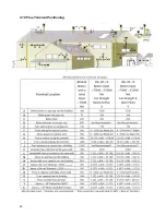
Page 40: ...40 9 10 Flue Terminal Positioning ...
Page 42: ...42 9 11 1 FIGURE 12 LINE G ...
Page 55: ...55 11 5 Ladder Logic Diagram ...
Page 56: ...56 11 6 Electrical schematics ...
Page 57: ...57 ...
Page 137: ......

