

111
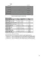
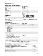
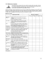
18.5 Start Up Checklist
Installation/start-up checklist
Venting information
Direct vent or using combustion air from indoor?
indoor / outdoor
Air inlet
Flue outlet
Diameter
Total length
Length horizontal
Length vertical
Length sloped at …..°
Number elbows 90°
Number elbows 60°
Number elbows 45°
Number elbows 30°
Air intake location (e.g. roof/wall)
Distance vertical from roof
Distance from (closest) wall
Common air intake system
(YES/NO)*
If YES => how many Air intake’s are joined?
Air intake (under)pressure (on top of boiler)
Possibility of dust/chemicals drawn in to air intake?
(YES/NO)*
If YES => of which kind?
Distance from Flue outlet (top of chimney) vertical
Distance from Flue outlet (top of chimney) horizontal
Is there a condensate drain installed to common flue system?
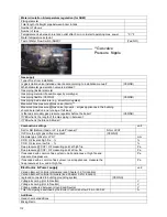
Flue outlet pressure (on top of boiler)
Condensate Drain
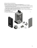
Check the level of the heat exchanger; It must have a slight angle from the rear to ensure
that the condensate drains from the heat exchanger.
(YES/NO)
Condensate trap (from package) installed according installation manual?
(YES/NO)
Inside diameter of drain piping
mm/inch
Is there a definite air gap between the condensate trap and the connection to drain pipe?
(YES/NO)
Total drop in height from boiler to drain piping exit point
Any additional trap points?
(YES/NO)
Perform PH test and register PH value
Condensate Neutralizer installed
(YES/NO)
Installer Information
Company
Engineer name
Address
Postal code
City
County
Telephone
number
Site Information
Site name
Site contact
(End user)
Address
Postal code
City
State/province
Telephone
number
Boiler information
Model
Serial number
Installation date
Cascade installation (Y/N)
(YES/NO)
Number of boilers
Type of boilers in cascade
After filling in form please send a copy by e-mail to:
[email protected].
Summary of Contents for S-CBX 105
Page 2: ......
Page 40: ...40 9 10 Flue Terminal Positioning ...
Page 42: ...42 9 11 1 FIGURE 12 LINE G ...
Page 55: ...55 11 5 Ladder Logic Diagram ...
Page 56: ...56 11 6 Electrical schematics ...
Page 57: ...57 ...
Page 137: ......


